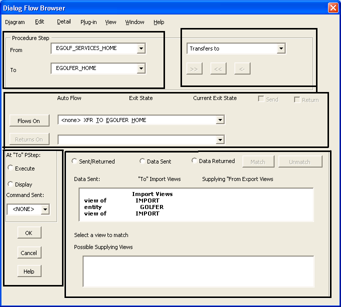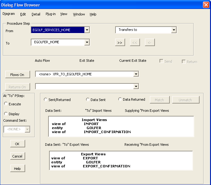

Let us look at the Dialog Flow Browser, which is used to detail the flows between Client procedure steps.
Follow these steps:
 icon to bring up the Dialog Flow Browser.
There are essentially five sections to the Dialog Flow Browser:

At the top, the browser displays the two procedure steps involved in the flow. In our case, we are flowing From: EGOLF SERVICES HOME (source) To: EGOLFER HOME (destination).
If we were using a Link type flow, we would have to define two of everything, since a Link essentially represents a two-way flow. We would have to specify two exit state values, two sets of actions to be taken, two commands, and two sets of view matching if necessary. We will still have to define two of everything, but only once, for each of the two Transfer flows we will define.
You may be thinking that we already set that exit state value in the eGolf Services Home procedure step. However, merely setting the exit state system attribute to some value does not automatically cause a flow. We have to add the flow (as we are doing now), and for each flow that we add, we have to define what value the exit state system attribute has to have in order for this particular flow to be taken. We can have multiple flows emanating from a procedure step, but only one will be taken upon completion of that procedure step, and it will be the flow with the matching flows on exit state value defined for it.
If this were a Link, the Returns On… exit state would be the exit state value the To: procedure step would need to set to initiate the return back to the From: procedure step.
In the top panel, which shows the import views in the destination procedure, select the IMPORT GOLFER. The bottom panel now shows the Possible Supplying Views (export views) from the EGOLF SERVICES HOME. Scroll down in the bottom panel if necessary and select EXPORT GOLFER and then select the Match push button. In the top panel you can now see the two matched views.

Note: When you add new objects to the Navigation Diagram, the diagram can show dashed or self-referencing lines, indicating a possible incomplete definition of some objects. To refresh the Navigation Diagram, close and re-open it.
|
Copyright © 2013 CA.
All rights reserved.
|
|