

System Output › Data Structure Diagram › Basic Components of the Data Structure Diagram
Basic Components of the Data Structure Diagram
The main component of the CA IDMS Schema Mapper data structure diagram is the record block. Each rectangular-shaped graphic represents a CA IDMS record and contains CA IDMS record fields. The upper left corner of the diagram is the origin (0,0). The coordinate position of each record block, relative to this origin, appears in the Cross-Reference Report.
- REC-NAME (record name) field identifies the name of the record type.
- The LOC-MODE (location mode) field identifies how records are physically located in their areas: CALC, VIA, or DIRECT.
- The LENGTH-MODE field identifies the record modes: F (fixed), V (variable), FC (fixed compressed), or VC (variable compressed). The value for this field is not stored in the dictionary in any literal sense. CA IDMS Schema Mapper determines the value as follows:
- A DEPENDS ON data element in the record indicates a variable length mode. Otherwise, the record is assumed to have a fixed length mode.
- The appearance of IDMSCOMP or IDMSDCOM in the list of procedures, which are to be invoked when the record is accessed, indicates a compressed length mode. Otherwise, the record is assumed to have an uncompressed length mode.
- The LENGTH (record size) field identifies the actual data length of the record (if fixed length), or the maximum data length of the record (if variable length), in bytes. If the value obtained from the dictionary is less than 1, CA IDMS Schema Mapper uses a value of 1 in the record block. This happens, for example, when a schema record is defined without any elements and is consistent with the value reported by IDMSRPTS for data length.
- The AREA field identifies the name of the area in which the record type is located.
- The DUPS-OPT (duplicates option) field identifies the disposition of records with duplicate control keys: DN (duplicates not allowed), DF (duplicates first), or DL (duplicates last). This field is blank for non-CALC records.
- The LOC-CTRL (location control) field identifies the CALC key name or VIA set name. This is always DIRECT-DBK for DIRECT records.
- The REC-ID (record identification) field gives the unique identification number of the record type.
- Groups of record blocks are connected by set connection lines, which show set relationships. Sets are identified by numbers in the CA IDMS Schema Mapper data structure diagram and are cross-referenced in the Cross-Reference Report. A unique number from 1 to n is assigned to each set, and the unique number appears with each set connection in the diagram as described below:
- When the set connection is a straight line, the number appears near the owner
- When the set connection has a set turn in it, the number appears near the owner and near the member
- For multi-member sets, the number appears near the owner and near each member of the set.
Record blocks that represent members of sets have arrows pointing toward them. Record blocks that represent owners of sets have arrows pointing away from them.
- The diagonal line that appears in the diagram for indexes contains the letters II when the line represents an integrated index.
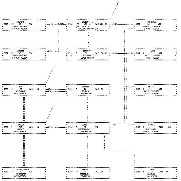
Exhibit 3.1: Sample of a Simple Data Structure Diagram
Copyright © 2013 CA.
All rights reserved.
|
|