

This section describes how nodes are connected in a CA IDMS DDS network.
Ports
In CA IDMS DDS, a connection between two nodes is defined in terms of a port. A port is an access point through which the node passes request and response packets to another node. A port is defined at system generation time by the resource name table (IDMSCSTB).
Note: For more information about ports, see Chapter 3, "CA IDMS DDS System Generation".
The resource name table tells the node the names of other nodes and the path used to reach each other node. For example, suppose node A is connected to node C by way of node B. To communicate with node C, node A sends a message to B for C. B receives the message, and forwards it to C. All A needs to know is that messages to C should be sent to B. That information is maintained in the resource name table.
Two types of connection
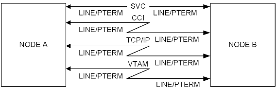
A CA IDMS DDS connection is represented in the network diagram by one of two different types of lines, depending on the type of connection between two nodes. A straight line represents an SVC connection, and a communication link represents either a CCI, a TCP/IP, or a VTAM connection. The LINE/PTERM pair that defines the node's port is placed beneath the line and near the node that uses the port. The following illustration shows the types of CA IDMS DDS connections and the information associated with the connections.
Coding node definitions
The resulting network diagram can be used as a basis for coding the DC/UCF system generation statements needed to define the node.
Note: For more information about coding these statements, see the CA IDMS System Generation Guide. A discussion of the CA IDMS DDS components included in a DC/UCF system generation is presented in Chapter 3, "CA IDMS DDS System Generation".
|
Copyright © 2013 CA.
All rights reserved.
|
|