

Although an application is ready for execution after the remote files are processed, we recommend that you test your application using the Diagram Trace Utility before introducing the application into your production environment.
The relationship of testing and running your application to the other required and optional IT tasks is described in the following illustration:
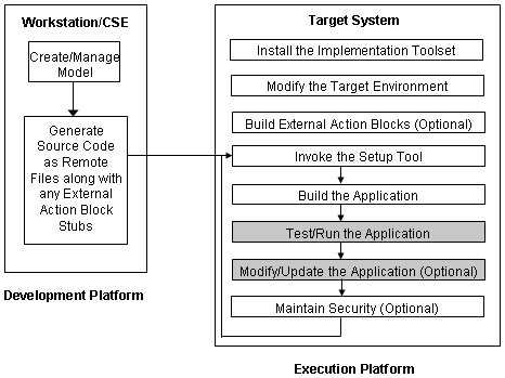
After an application is built successfully, it is ready to run. Running an application starts the application servers in the Pathway environment. After the application servers are loaded, they can be accessed through the AEF, the non-TCP Requester, or RSC/MP (for Distributed Servers).
Follow these steps:
VOLUME $<setvol>.<setsubvol>
PWCOLD
This command cold-loads a newly created Pathway environment. The application starts running.
After you finish running the application, you can stop it.
Follow these steps:
VOLUME $<setvol>.<setsubvol>
The application stops running.
For Block Mode applications, you do not have to enter information directly on the screen as the startup parameters supply information to the executable procedure. The executable procedure must be an online procedure and must be defined as one that accepts clear screen input. Clear screen input is defined with the Dialog Flow Diagramming Tool.
Clear screen input can be accepted by both the AEF and the non-TCP Requester. The clear screen input consists of one or more parameters separated with the appropriate string and parameter delimiters. You can define the string and parameter delimiters through Business System Defaults.
Note: For more information about clear screen input, see the Block Mode Design Guide.
The parameter list is defined by keywords. Keywords are labels that identify the parameter and must be accompanied by the parameter data enclosed in delimiters.
The format for parameters is:
KEYWORD1 data1, KEYWORD2 data2 . . .
Defines the keywords.
Identifies the keyword separator or data separator.
Defines the data associated with the keyword to be used by the executable procedure.
Identifies the parameter delimiter.
If spaces are not selected as the parameter delimiter, they are ignored. The keyword can be the prompt that associates the field on the screen to the procedure step, or a label that associates the field to the procedure step. All keywords must be unique.
When using keywords, the parameters entered need not be in the same order as the parameter list defined for the screen. For example, the following two clear screen inputs are equally acceptable:
NAME Mary Valdez, NUMBER 123-45-6789
NUMBER 123-45-6789, NAME Mary Valdez
Keywords are case-sensitive and cannot contain delimiters. However, you can append symbols. For example, you can append an equal sign (=) to the keyword NAME. The result would appear as NAME=Mary Valdez.
If you do not define parameters with a keyword, you must enter the parameters in the same order as they are defined in the list on the Dialog Flow Diagram.
Two parameters predefined to CA Gen procedures are RESET and RESTART. These parameters apply only to online procedures of Block Mode applications. You must specify in the Environment Tool if you want your application to support the RESTART parameter.
The RESTART parameter lets you redisplay a dialog that was interrupted. RESTART restores all data to the screen, which was present when the interruption occurred. RESET allows you to display a screen again by starting the dialog at the beginning. Data from the interrupted dialog is not restored to the screen.
Note: For more information about RESET and RESTART, see the Toolset Help.
Non-TCP requesters can supply additional initial data to application servers.
The Application Execution Facility (AEF) is an environment that lets you execute CA Gen Block Mode applications on NonStop. The AEF is tightly based on Pathway and provides the following functionality:
In addition, the Pathway architecture provides the following functionality:
You can access AEF using the following devices:
NonStop 6530-type terminals can be attached to the AEF using the following transport protocols:
Terminal emulators that support the 6530 block-mode protocol are also supported.
Since Pathway supports IBM 3270-type devices, you can connect such devices (or compatibles) to the AEF using the following access methods:
IBM 3270-type devices must be secondary devices on the line. The NonStop server must be the primary device through the SNAX line.
Follow these steps:
VOLUME $<setvol>.<setsubvol>
The AEF screen appears.
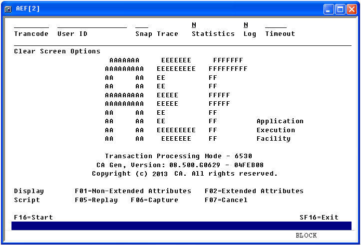
The AEF screen contains the following input fields:
The trancode with which the application will start. This is a required field.
(Optional) Overrides the default user ID for the current AEF session.
(Optional) Specifies the level of information logged to an internal trace file. This log file is created in the base target subvolume and is named lgxxxxxx (where xxxxxx is the process ID of the running server). A value between 0 and 31 is provided—the higher the value, the more information will be traced. A trace value of 31 may consume a large amount of disk space, which can significantly slow processing.
Note: Use of the Snap Trace field should be for development purposes and only under the direction of Technical Support to locate problems.
(Optional) Indicates to collect transaction statistics and record them to the STATIS file located in the base target subvolume.
Values: Y or N
Default: N
(Optional) Indicates whether the AEF Requester will log all encountered error conditions to the EMS log.
Values: Y or N
Default: N
(Optional) Specifies the amount of time given in seconds before the application is terminated.
Default: No default value
Identifies the input supplied to the executable procedure.
Note: For more information, see Application Startup Parameters (Block Mode only).
Upon exiting from the application, the load module terminates and control returns to the AEF.
Only Block Mode applications built as transactional are invoked using the AEF. Command line applications are invoked through a non-TCP requester.
Note: Function key assignments for the AEF may differ for each terminal device.
The AEF uses a keyboard mapping file to assign values to each function key and special purpose key available for use by any generated applications that reside on your target system. The following files are available for use:
The following components are available in AEF:
The following illustration shows the interaction of the AEF components:
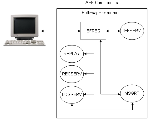
The AEF components are described in the following sections.
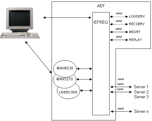
The AEF Requester (IEFREQ) is a program that runs through the Terminal Control Process (TCP) and implements the following functions:
IEFREQ is responsible for routing incoming transactions to the appropriate application server class. It can communicate with the following servers:
IEFREQ is structured so that it can be incorporated into an existing Pathway application. It logs error conditions to the Event Management Subsystem (EMS) through the Error Log Server (LOGSERV).
The IEFREQ program must be the terminating SCOBOL program in a calling sequence; that is, the IEFREQ program does not support calling child SCOBOL programs.
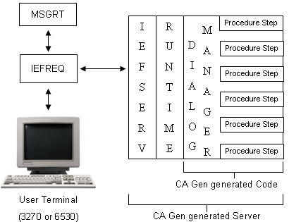
The following illustration shows how IEFREQ interfaces with user-written requesters, application servers, and the AEF supported servers:
To understand the role of the AEF Server Interface (IEFSERV), this section describes a CA Gen generated server, of which IEFSERV is a part.
The CA Gen generated server is comprised of three parts:
The IEFSERV is bound to the CA Gen runtime and the CA Gen generated code to create an application server. The application server is a server class in the Pathway environment. A different server class is generated based on the load module packaging that occurs within the Business System design.
The IEFSERV and the CA Gen runtime are delivered as part of the Implementation Toolset while you develop the CA Gen generated code. All three components are linked together during the build of an application by the Setup Tool.
IEFSERV is a collection of routines that reads and replays messages through $RECEIVE, handles all the CA Gen intrinsic functions, handles the overflow file, and reports errors to LOGSERV.
The following illustration provides the basic structure of the CA Gen generated server:
The Message Router Server (MSGRT) is a server that implements Transaction Mapping functions.
On initial startup, MSGRT loads the Transaction Mapping Table (TMT) into extended memory. This improves the performance of the binary search that the message router uses to find a transaction code. If a change in the CA Gen procedure step packaging is required, the message routers must be stopped.
MSGRT locates the incoming transaction code from the input data stream, and performs a table lookup (from the TMT) to map the transaction code to the CA Gen server class responsible for handling that business function.
The TMT is defined to MSGRT as a define called =TMT. The definition of =TMT is included in the default DEFINES file created during the build of an application using the Setup Tool.
The TMT holds a set of transaction codes associated with executable load modules. This table resides in the application's target location. There is one TMT for each application. During application execution, this table is read into memory for performing lookups to ascertain the appropriate server that handles a particular transaction.
Each transaction code must be unique within each TMT. If the transaction codes are not unique, you may encounter problems during load module execution. The TMT can store up to 1024 transaction codes.
The TMT is comprised of the following columns:
TID                CHAR(8) NO DEFAULT NOT NULL
SERVER_CLASS_NAME  CHAR(15) DEFAULT NULL
MODEL_NAME         CHAR(32) DEFAULT NULL
Example:
> volume $VDATA3.ABLK11
> sqlci
>> select * from tmt;
TID       SERVER_CLASS_NAME   MODEL_NAME
--------  -----------------   ----------------------
P130      P130                PT ABLK TEST MODEL 11
P131      P131                PT ABLK TEST MODEL 11
P132      P132                PT ABLK TEST MODEL 11
P133      P133                PT ABLK TEST MODEL 11
P134      P134                PT ABLK TEST MODEL 11
--- 5 row(s) selected.
>> exit
The Error Log Server (LOGSERV) is a server that implements the error logging function.
LOGSERV is the CA Gen gateway to the EMS software running on NonStop. LOGSERV subsequently formats the message into a tokenized message for routing to an EMS collector ($0 by default) through the EMS subsystem. Events can originate from IEFSERV, IEFREQ, or MSGRT.
CA Gen system messages are visible with operation management products such as ViewPoint.
The AEF can record and playback a session with an application. You can play the recording at a later time only if the database associated with the application has not been changed.
The Replay Server (REPLAY) records and replays transactions. These transactions are stored in the SQL table named RECAP. The RECAP table is defined to REPLAY as a define called =RECAP. The definition of =RECAP is included in the default DEFINES file created during the build of an application using the Setup Tool.
Perform the following steps to record transactions.
Follow these steps:
An overlay will be displayed at the bottom of the screen.
The transaction is recorded.
Perform the following steps to replay a recorded session.
Follow these steps:
The recorded transaction is replayed.
The RECAP table is comprised of the following columns:
USER_ID          PIC X(16) NO DEFAULT NOT NULL
CAPTURE_ID       PIC X(8) NO DEFAULT NOT NULL
SEQ_NUM          PIC 9(5) COMP NO DEFAULT NOT NULL
TERMINAL_TYPE    PIC 9(4) COMP NO DEFAULT NOT NULL
TERMINAL_SUBYPE  PIC 9(4) COMP NO DEFAULT NOT NULL
DATA_LENGTH      PIC 9(5) COMP NO DEFAULT NOT NULL
TERM_DATA        PIC X(4000) DEFAULT NULL
Example:
> volume $VDATA3.ABLK11
> sqlci
>> select * from recap;

USER_ID           CAPTURE_ID  SEQ_NUM     TERMINAL_TYPE  TERMINAL_SUBYPE  DATA_LENGTH
----------------  ----------  ----------  -------------  ---------------  -----------
TERM_DATA
----------------------------------------------------------------------------

002-ZN018-000     FRED                 0             49               50           26
V!(/P120P120S5

002-ZN018-000     FRED                 1             49               50           23
B!  P123P123SY
002-ZN018-000     FRED                 2             49               50           26
V!(/P120P120S4
002-ZN018-000     FRED                 3             49               50           23
B!"!P122P122SY
002-ZN018-000     FRED                 4             49               50           26
V!(/P120P120S6
002-ZN018-000     FRED                 5             49               50           71
V!2:P124P124SY 111111111111111111+ 444444444444444444

002-ZN018-000     FRED                 6             49               50           23
B!&#P124P124SY
--- 7 row(s) selected.
>> exit
The Statistics Server (RECSERV) is a Pathway server that implements the Time Recording function. It collects transaction statistics and records them in the STATIS file.
RECSERV is activated by IEFREQ through flag settings in the configuration parameters (set the Statistics flag on the AEF Main Menu to Y). RECSERV logs errors to LOGSERV.
The STATIS file is comprised of the following fields:
Transaction ID     char[9]
Initial Time       char[9]
Ending Time        char[9]
Bytes to Server    char[6]
Bytes from Server  char[6]
Terminal Name      char[17]
Server Name        char[16]
Example:
P530     11044293 _11044299 _00078 _01099 _002-ZN018-000 P530
P532     11045051 _11045059 _00027 _01685 _002-ZN018-000 P530
P532     11045725 _11045732 _00031 _00917 _002-ZN018-000 P530
P530     11050129 _11050133 _00026 _01099 _002-ZN018-000 P530
This file is an editable file (file code 101).
The following sections describe application testing and the procedure required to access and use the Diagram Trace Utility.
The Diagram Trace Utility is used to test a generated application before it is moved to a production environment.
The Diagram Trace Utility provides a number of special capabilities that allow you to view CA Gen model elements used to build an application (such as Action Diagram statements) while the program is being executed. To use the special capabilities of the Diagram Trace Utility, you need to make certain selections when remote files are generated. These selections cause the generation of the additional code required to implement the special capabilities available through the Diagram Trace Utility.
The portions of the application that are to be tested must be generated with trace enabled to communicate with the Diagram Trace Utility.
Before an application can be tested, certain application components must be built using the Setup Tool:
You must use the Diagram Trace Utility to test a generated application.
Note: Ensure that NonStop TCP/IP is installed and running for TCP/IP connectivity before using the Diagram Trace Utility.
Follow these steps:
xx is the current CA Gen version installed on your system.
The Diagram Trace Utility automatically starts listening on port 4567. You can change the default port in the Diagram Trace Utility.
Note: For more information about changing the default port, see the Diagram Trace Utility User Guide.
Default: $ZTC0
Note: There may be more than one TCP/IP process running on a system. Contact your system administrator to find out the name of this process.
All servers must have the same =APPLICATION_INI and =TCPIP^PROCESS^NAME DEFINES settings.
Example: The following example is a sample of the proposed DEFINES:
SET SERVER DEFINE =APPLICATION_INI,CLASS MAP,FILE $DATA1.PROXYX.APPLINI
SET SERVER DEFINE =TCPIP^PROCESS^NAME,CLASS MAP,FILE $ZB018
Note: PWCOOL will not always work because of the changes made to the Pathway server configuration files.
The Diagram Trace Utility is ready for use.
|
Copyright © 2015 CA Technologies.
All rights reserved.
|
|