

Testing Comm. Bridge Connections › Testing Connectivity Using a DPC Application
Testing Connectivity Using a DPC Application
The testing of a particular Comm. Bridge can be accomplished using a DPC application that targets a DPS that is deployed to the specific target server execution environment being served by that Comm. Bridge. The DPC would need to be generated for, or be configured to use, TCP/IP (Sockets) as its transport mechanism. The DPC initiates a test request to a particular Comm. Bridge by designating that Comm. Bridge's Host and Port information as defined by the target Comm. Bridge client side configuration.
The following diagram illustrates using a DPC to drive the testing of a Comm. Bridge:
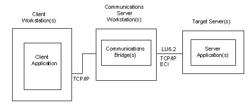
The following steps can be used to drive the testing of a particular Comm. Bridge.
- The target DPS must be installed to the specific server the Comm. Bridge being tested is configured to serve. See the Comm. Bridge Server Side configuration information to determine the specific target server execution environment the Comm. Bridge is configured to serve.
- Configure the Comm. Bridge client side configuration. See the chapter "Comm. Bridge General Configuration" in this guide. Note the Comm. Bridge client configuration is a well-known Port number.
- On the DP client workstation, configure the DPC application to access the Comm. Bridge by configuring the DPC to communicate to the Host name and well-known port of the target Comm. Bridge. The socket information associated with the Comm. Bridge being tested can be configured into a generated DPC or be specified using one of the CA Gen support commcfg files. See the Distributed Processing – Overview Guide for details of how to override a generated client configuration at runtime.
- On the client workstation, activate the client application and exercise the application as required to initiate a cooperative flow that will target the Comm. Bridge being tested.
- The cooperative flow request should result in a connection request to the Comm. Bridge. The Comm. Bridge will process the inbound cooperative flow request. If the Comm. Bridge already has a connection to its associated target server execution environment the connection is used, otherwise a new connection will be created from the Comm. Bridge to the target server environment.
- Both the client and server connection status can be monitored from the Comm. Bridge main window. The Status field reflects the status of the server connection. The Client Name contains a list of those clients currently connected to the Comm. Bridge.
- Verify the test cooperative flow worked as expected.
If errors are encountered, use the information found in the Comm. Bridge log file to determine the cause of the failure. Access the log file by selecting File,Browse,Log File from within the Comm. Bridge application. Log files created by the client and/or the target server may also be needed to fully determine the cause of a communications failure.
Copyright © 2013 CA.
All rights reserved.
|
|