

As a Backbone Administrator, you want to set up a grid on the BFC. To control communication between the server and grid controller, storage access for appliances, and private inter-appliance communications, CA AppLogic uses a private network. On a public network, a grid uses the server public, application, and controller IP addresses. You use the New Grid Wizard and then you add users and configure group privileges to the grid.
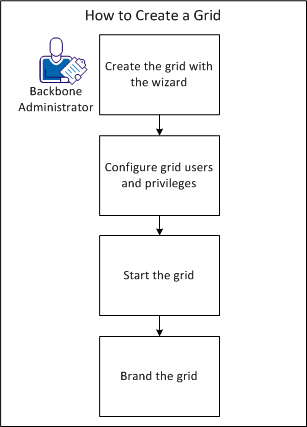
The following diagram shows how you set up a grid on the BFC:
To create a grid, use the New Grid Wizard. You can open the wizard from the Grids page to guide you through the grid creation.
Follow these steps:
The General page of the wizard appears and specifies the grid name and license information.
Important! Provide an alphanumeric name that does not contain spaces.
The Version page appears and specifies the CA AppLogic software version with hotfixes (if any) to install on the grid.
If a hotfix exists for the version you selected, the name of the hotfix appears in the Hotfixes list.
The Xen page appears and specifies the minimum requirements for Xen server hardware for the grid. You can also use tags to designate server allocation.
You can specify different values for VMware grids in the next page of the wizard.
You specify a choice to establish the relationship that indicates Member of or Not a member of. This relationship refers to the tag that you indicate in the Tag/Property field.
For example, indicate membership in more than one tag, or you can restrict membership to specified tags.
Note: This area only lists free servers and does not list quarantined servers.
The VMware page appears and specifies the minimum requirements for VMware server hardware for the grid. You can also designate server allocation using tags.
You specify a choice to establish the relationship that indicates Member of or Not a member of. This relationship refers to the tag that you indicate in the Tag/Property field.
For example, indicate membership in more than one tag, or you can restrict membership to specified tags.
Note: This area only lists free servers and does not list quarantined servers.
The Network Resources page appears and specifies the IP ranges to allocate for the grid for use by applications and the controller IP. If you optionally use VLAN tagging, you can select IP ranges from the ranges that you created in the Networks tab of the Administration page.
Select a VLAN from the drop-down list. The VLANs you configured in the Administration page display in this list. You can choose not to include VLANs in your network resources.
Note: If you have not defined VLANs in the Administration page, the value for VLANs displays "None (untagged)".
The Start, End, and Scope fields auto-populate based on the network you select. You can change these fields as necessary.
The Controller IP must specify an IP that is in one of the defined external networks on the networks page, but cannot be in the range of application IPs defined for the grid. For example, the grid can have application IPs of 111.222.111.10 - 20, and a grid controller IP 111.222.111.9, but not a grid controller IP of 111.222.111.10.
The controller IP can only be selected from non-shared application IP ranges defined in an external network. Add non-shared application IP ranges in the selected network.
The Controller page appears and specifies the grid controller information. For example, the grid ID, grid controller userID and password, and the desired OEM kit to use.
You are required to retype the password in a separate field.
You are required to retype the password in a separate field.
For example, you enter the account_id, account_key, ctl_blk_copy, and reference for the Backbone LAN.
The Storage page appears and specifies striping options and parameters for external storage settings.
Important! The external storage share must be configured to route traffic to the 192.168.<grid ID>.0/24 networks through its interface on the grid backbone network. Configure the external storage before add grids, or the grid creation fails.
The test attempts to contact the external storage at the indicated location. A message displays with test results.
The Authentication page appears and specifies the default authentication for Role Based Access Control RBAC), such as Local, LDAP, or Active Directory.
Note: If you select LDAP as the authentication method, then a global user is only recognized in the global directory service if its entry uses one of the following basic object classes for a person: person, inetOrgPerson, or organizationalPerson.
A group in the global directory service is only recognized if its entry uses one of the basic object classes for a group (groupOfNames and groupOfUniqueNames).
(Optional) Select whether to use Transport Layer Security (TLS) to access the directory service using an encrypted connection.
This field indicates the time since a global user last authenticated with the global directory service. During this time, the user can authenticate locally in the event the global directory service is unavailable.
The grid appears in the list immediately, but the grid creation process can take a couple hours to complete. You can hover your mouse over the animated grid status icon to monitor the progress of the grid creation.
You connect to the grid in your browser through the grid URL or Grid Controller IP address. You can add a user to the grid, add a user to a local group, and grant a user administrator privilege. You can also add SSH keys for a grid.
Follow these steps:
create user firstname.lastname@myaddress.com pwd=-
The user is assigned to a local role-based access group named all. This group does not have an explicit list of members, but includes all users as a member implicitly.
group modify groupname +local:user:firstname.lastname@myaddress.com
The grid modify_acl command lets you add a grid user to the grid_administrator group.
grid modify_acl local:user:firstname.lastname@myaddress.com=grid_administrator
You can grant a user access by pushing SSH keys to the grids. The /root/.ssh/authorized_keys file stores two keys named <random text>root@<bfc host>.
SSH keys have the following format:
ssh-rsa AAAAB3NzaC1yc2EAAAABIwAAAQEAtdsF6rxRPvi3aKciQ1J+7yZTgAXDVkNZDRzZPzpEtAak+tnroXS6RvwUOv8Oa9toCjlEIol1EuvaYBryzmRqH5cdm9UKXJjNZ5fnF7fhz928wcCHrHYebtOWGdqXi03MFt0Q4ytZI0+xnjS5iZkaJLW1IAoNLVQdrjUWhH4f+GIJ58jg7xpp3aORQ/zCnXWzxMJs78rX3LkbVW5EftzUZZowVSRVrO6JRq3/7sMzktKDHbB4Am2WoxzceA36NxPQsg7gcao5BPGAvJg2B1MnBdVBIy5gSYuPNtjjpfHboZWWd4cywZ+uIlOFIJy0GGIizrdza351MX7PuZ/YZulffw== root@bfccontroller
The Grids page appears.
The key is pushed to the grid.
You can start or stop a grid as necessary. If you stop a grid, the BFC powers off the grid servers. The grid cannot come back online until you restart the grid.
Important: If applications run on the grid, verify that you stopped them in the product system dashboard before you stop the grid.
Follow these steps:
The Grids page appears.
You can customize the appearance and selected elements of the product GUI. You can use a custom logo when a user logs in to the GUI. You can also replace the available links on the grid dashboard support page.
Follow these steps:
The Administration page appears.
Specifies a name for the OEM kit file. This name appears in the OEM Kit drop-down list when you create a grid.
Indicates to use the OEM kit as the default kit when you create a grid.
Specifies the TAR file that contains an oem.conf file and an optional banner.png or banner.jpg file.
The grid is branded.
You have successfully created a grid. You can perform grid configuration tasks.
|
Copyright © 2013 CA Technologies.
All rights reserved.
|
|