

As a backbone administrator, you use the Configuration Checklist to configure your network after the Backbone Fabric Controller installation completes. The Checklist displays all the required and optional items that must be configured before grids can be created. The configuration items are verified and a checkmark displays as they are completed. If all of the required parameters are configured, close the checklist.
If one of the optional or required parameters is not complete, the checklist display each time you log in to the BFC. In addition, all the required parameters are also checked when a new grid is created. You can create a grid after the configuration items are complete.
You can also use the Grid Planning Chart to better understand how to configure your network.
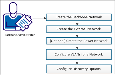
To configure the network, follow these steps:
You must have create a backbone network before you can create your grids. CA AppLogic only supports one backbone network. Typically, the address of the backbone network is 192.168.0.0/24.
Follow these steps:
The Administration page opens.
The Add a Backbone Network dialog appears.
Base IP address of the network.
The length of the subnet bits in the netmask. There is a one-to-one correlation between CIDR prefix length and the traditional IP netmask. For example, 24.
The Configure New Network dialog appears.
IP range for the grid.
The Start, Stop, and Size fields auto-populate based on the network you select. You can change these fields as needed.
First IP in the IP range for the grid.
Last IP in the IP range for the grid.
You must have at least one external network before you can create your grids. Use this procedure to create the external network.
Follow these steps:
The Administration page opens.
The Add an External Network Dialog opens.
Network address of the subnet and this address is not used for assigning to any other nodes. For example, 155.35.86.0.
The length of the subnet bits in the netmask. There is a one-to-one correlation between CIDR prefix length and the traditional IP netmask. For example, 24.
Gateway network address of the external network. Gateway IP is required only for networks that allow access beyond the subnet, but you may have it defined on “private” networks too if desired. For example, 155.35.86.1.
The Configure New Network dialog opens.
Specifies the IP range for the grid.
The Start, Stop, and Scope fields auto-populate based on the network you select. You can change these fields as needed.
Specifies the first IP in the IP range for the grid.
Specifies the last IP in the IP range for the grid.
Indicates whether the range is hardware or application related for external networks.
Specifies whether the application IP range or subrange can be used by multiple grids. Click the check box to enable sharing. Shared application IP ranges can be used to migrate an application from one grid to another without changing the application IP. It can also be used for load balancing or to move workload so a grid can be upgraded.
The Network Resources page of the Add Grid wizard and the Edit Networks dialog contain a Shared column that displays whether a network is Shared or Exclusive.
Note: The hardware and application IPs do not have to be on the same network. If you want to configure a different network for each, repeat steps 3 through 7 and specify the opposite scope in step 7.
CA AppLogic creates the external network.
If your grid nodes have IPMI capability, you can specify power network settings for your grid network from the BFC. The power network settings allow the BFC to intelligently control the power management operations (such as, power cycle and power off) on grid nodes.
Note: If your nodes have IPMI enabled, then you need to specify the Power IPs of those nodes in the power network.
Follow these steps:
The Administration page opens.
The Add an External Network Dialog opens.
Network address of the subnet and this address is not used for assigning to any other nodes. For example, 192.168.0.0.
The length of the “subnet” bits in the netmask. There is a 1-1 correlation between CIDR prefix length and the traditional IP netmask. For example, 24.
Gateway network address of the external network. Gateway IP is required only for networks that allow access beyond the subnet, but you may have it defined on “private” networks too if desired. For example, 192.168.0.1.
A new page opens where you can specify the following fields with the correct set of IPs.
IP range for the grid.
The Start, Stop, and Scope fields auto-populate based on the network you select. You can change these fields as needed.
First IP in the IP range for the grid.
Last IP in the IP range for the grid.
You can add and configure VLANs for a network on the Administration page, Networks tab, External tab. After you add a VLAN, you can select IP ranges you have specified in the VLAN for creating tagged VLAN grids. You can create multiple VLANs associated with a subnet with overlapping IP ranges. Generally, this allows you to reuse IP addresses provided that the IPs are not routed outside the BFC environment.
Note: Do not mix tagged VLANs and non-VLAN networks on the same grid.
Follow these steps:
The Administration page opens.
For each network, a VLANs button appears at the end of the row.
The VLANs dialog opens.
The Add a VLAN dialog opens. Specify the following information:
Specifies the VLAN ID.
Lists the name of the network you are working with.
A dialog opens that allows you to indicate VLAN parameters.
The Add/Edit IP Range dialog opens. Indicate the following parameters for the VLAN:
Indicates the IP range to use. Select a range from the drop-down list.
The Start and End fields are populated based on your choice. Accept the defaults or edit the fields.
The Add/Edit IP range dialog closes and you return to the VLAN parameters page.
The VLAN parameters page closes and you return to the VLANs dialog.
The VLANs dialog closes and you return to the Administration page.
You can now assign your VLAN and corresponding application IPs to a grid when you create a new grid, or work with grid properties on the Network tab of the Grid properties page.
The BFC enables you to configure the Automatic Discovery feature for the current backbone network as needed. Automatic Discovery is off by default.
Follow these steps:
The Administration page opens.
Note:When the server discovery is off, new servers are not discovered when they are powered on. In addition, server discovery must be turned off before you can specify the Discovery Mode.
You are prompted to turn on Server Discovery.
Note: Discovery lists can only be edited while discovery is off. If you decide to change the discovery mode later, any existing quarantine lists you created are deleted.
|
Copyright © 2013 CA Technologies.
All rights reserved.
|
|