

CA 2E automatically creates a default interactive panel design for each interactive device function. You can modify the default designs to meet the requirements of your application.
A device design specifies:
These are the defaults from the design model; however, you may override most of them.
You can view the default device design from the Edit Function Details panel by pressing F9 as shown in the following example:
EDIT FUNCTION DETAILS My model
Function name . . : Edit Horse Type : Edit file
Received by file. : Horse Acpth: Retrieval index
Workstation . . . : NPT
Source library. . : MYGEN
Object Source Target
? Type Name HLL Text
PGM MYAEEFR RPG Edit Horse Edit file
DSP MYAEEFRD DDS Edit Horse Edit file
HLP MYAEEFRH UIM Edit Horse Edit file
SEL: E-STRSEU, O-Compiler Overrides, T-ILE Compilation Type (*PGM/*MODULE)
F3=Exit F5=Action diagram F7=Options F8=Change name
F9=Device design F17=HTML skeleton F20=Narrative
The default panel design for the Edit Horse function displays as shown in the following example:
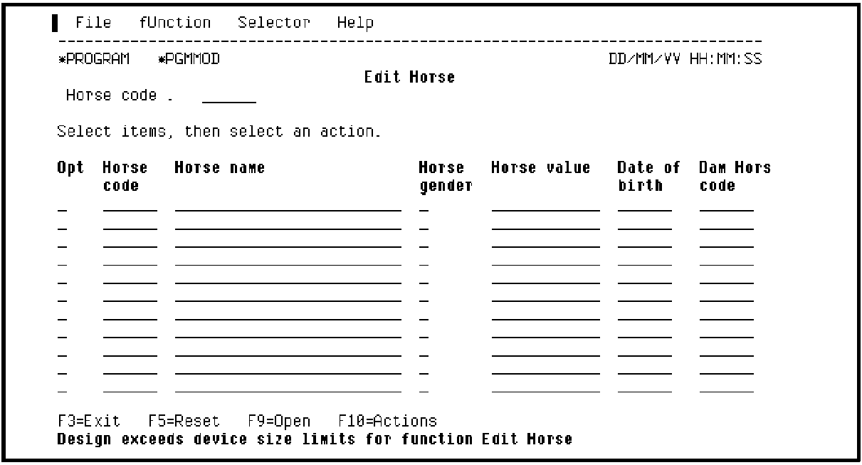
If you want to change the position of a field on the device design, position the cursor on the chosen field and press the F9 function key. For example, to begin the second line with Dam Horse code, you just place the cursor on this field and press F9.
The subfile record format splits into two lines and the device design is updated to reflect the change.
Position the cursor as shown in the following example:
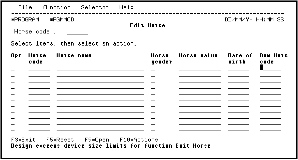
Press F9. The subfile record format now displays only two HORSE records as shown in the following example:
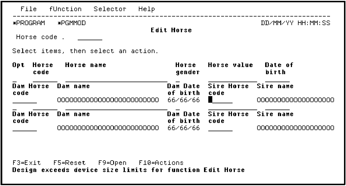
You can repeat the process to move the fields relevant to the Sire to a separate line from those for the Dam by placing the cursor on the Sire Horse code and pressing F9.
For more details on modifying the device design, see the Tutorial.
|
Copyright © 2014 CA.
All rights reserved.
|
|