

These are the steps for analyzing process logic:
This is the first step in creating the Process Logic Diagram. You can use this diagram to sketch out process logic before specifying it precisely in the Action Diagram.
The general approach to building a Process Logic Diagram is to superimpose actions to be performed in the process on a subset of the Entity Relationship Diagram, showing entity types to be affected.
The purpose of this step and Step 2 is to scope this Entity Relationship Diagram fragment.
The sample process used in this discussion is the Take Order process. The relevant Entity Relationship Diagram fragment is an expansion of the one shown in the Entity Relationship Diagram fragment for the process Take Order.
The primary entity types are either already identified as the objects to be worked on by the process, defined as expected effects of the processes, or, simply those entity types that immediately spring to the mind of the analyst when visualizing the process.
With the Take Order process, for example, the entity type order is obviously required. Even if the requirements for product, order item and customer do not occur to you, you can identify them in the next step. At this point, you need to at least note that Take Order uses the entity type order.
If you follow the parallel decomposition approach, you will often find that the primary entity type is the central entity type in its subject area, which is naturally the first place to begin the next step. The chapter "Building the Analysis Model" describes the parallel decomposition approach.
To finish developing the Entity Relationship Diagram subset, you must inspect the neighborhood of the primary entity types to find additional entity types required by the process.
The neighborhood of an entity type is the set of all entity types directly related to the subject entity type.
For each such entity type discovered, you also examine the neighborhood of that entity type. This activity is repeated until the neighborhoods of all affected entity types have been considered.
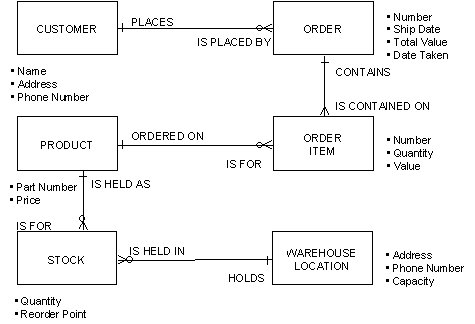
Step 1 identified ORDER as the only primary entity type for this process. Based on the illustration perform these steps:
According to the illustration, CUSTOMER has only one entity type in its neighborhood, the original primary entity type order. Since you have already identified order as important and since customer has no more relationships, that set of neighborhoods is exhausted.
Besides order, order item has one entity type in its neighborhood: product. Since the kind of product ordered on an order item can only be identified by the pairing of the order item with a product, clearly product is important to Take Order also. Record this fact.
The relationship membership order item is for product, is mandatory. This indicates that you must establish the pairing between order item and product in the same elementary process in which the order item is created.
Besides order item, the only entity type in the neighborhood of product is stock. After careful consideration, you and the business staff determine that order taking does not change stock levels. Thus, stock is not important to the Take Order process. This is a simplified example. In practice, Take Order may alter an attribute of stock called Free Stock Level.
Because none of the elements of the neighborhood of product is important to Take Order, you have exhausted all potential neighborhood entity types.
The entity types discovered during this step are:
The final activity in Step 2 is to draw a fragment of an Entity Relationship Diagram showing the entity types required for the process.
Usually, the set of entity types with which a single process deals is small enough to be contained in a page print or plot from the Entity Relationship Diagram. In the Take Order example, the Entity Relationship Diagram fragment and the expanded Entity Relationship Diagram fragment both happen to show the exact required subset of the Entity Relationship Diagram. If information views have already been analyzed, this set of entity types should resemble the composite list of import and export views of the process. You must resolve any anomalies, such as an entity type missing from this diagram but listed as an export view.
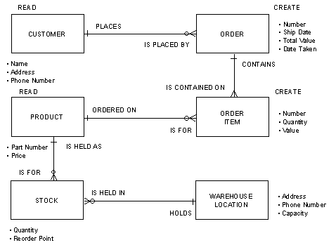
In this step, you annotate the Entity Relationship Diagram with the actions to be performed on the identified entity types. These actions should be significant for the business; actions to correct data errors, for example, should be left for the system designer.
These are the entity actions that may be performed:
Delete is very rare in business. For legal, audit and statistical purposes, entities are usually updated to "inactive" status or placed in an inactive termination state a nd not deleted until (often years later) a separate administrative process discards entities that are no longer needed.
The entity actions required in the Take Order process are:
This list of actions on entity types contains exactly the same information as the expected effects of the process. If expected effects have already been recorded, you should verify them against this list.
CA Gen reflects the content of an action diagram for an elementary process in the expected effects of that process, but in the case of product, the action diagram contains a Read statement, for product, and the expected effect is Update because the set of product relationship memberships is modified.
The following illustration shows the annotated Entity Relationship Diagram fragment, from now on referred to as a Process Logic Diagram, for the Take Order process.
The Create and Update entity actions may have attribute and relationship membership actions subordinate to them. In this step, you identify these subordinate actions and update the Process Logic Diagram to show them.
In the Take Order process, Create actions operate on two entity types: order and order item. Assume that the attributes of those entity types have the optionality shown in the following table:
|
ORDER |
Optionality |
|
NUMBER |
(mandatory) |
|
SHIP |
(optional) |
|
DATE |
(mandatory) |
|
TOTAL |
(mandatory) |
|
VALUE |
|
|
DATE |
|
|
TAKEN |
|
|
ORDER ITEM |
Optionality |
|
NUMBER |
(mandatory) |
|
QUANTITY |
(mandatory) |
|
VALUE |
(mandatory) |
The only optional attribute of either order or order item is Ship Date. You must set all mandatory attributes of both order and order item in the statements that Create them.
As for Ship Date, it will probably not be set until the order is filled and shipped, so it is not set in the Take Order process.
The following illustration shows the Process Logic Diagram for Take Order annotated with subordinate attribute actions to the Create actions for order and order item.
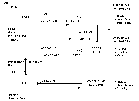
Also in the example based on the illustration of the Entity Relationship Diagram fragment for the process Take Order, the relationship between order and order item is fully mandatory. Assuming that you create an order before its order items, the Create for order cannot include an Associate to order item; the order item does not yet exist. You must establish the relationship between order and order item when each order item is Created.
The rule to remember is that all mandatory relationships must be established by the time the elementary process finishes executing. An individual entity action might leave things inconsistent for a moment, but the total collection of actions that form a process must leave the business in a completely consistent state.
For the Take Order process, you must consider the relationships of order and order item. It so happens that each relationship membership of order and order item is mandatory so they must all be established. The Process Logic Diagram for Take Order after detailing actions shows the Process Logic Diagram for Take Order, annotated to include attribute and relationship actions.
After identifying all actions on entity types, attributes and relationships, you can determine the sequence in which those actions should be performed during process execution. This sequence is recorded on the Process Logic Diagram by numbering each of the entity and relationship actions to be specified.
Before two entities can be paired, they should both be available through a Read or a Create. In general, you specify Read actions for existing entities and then Create actions for entities with which they will be paired.
Sometimes the sequence of actions is irrelevant. This situation typically occurs when sets of actions can either be performed in parallel with, or exclusive of, one another. In such cases, you must assign an arbitrary sequence to the actions in question.
Process Logic Diagram notation is primarily oriented to showing a linear sequence of entity actions. If necessary, the notation can be extended to show details of conditional, repetitive, or recursive processing, as shown in the illustration of the Process Logic Diagram for Take Order after detailing actions.
Before entities can be Read, a set of criteria for selecting them from among other entities of the same type needs to be established. In this step, you identify these criteria and use them to annotate the Process Logic Diagram.
Selection criteria can include any combination of:
You develop selection criteria by combining these elements using a series of ands and ors to fully identify the entity to be retrieved. For more information about developing selection criteria, see the Read action statement in the toolset documentation.
In the Take Order example, entities of two types will be Read:
The following illustration shows the Process Logic Diagram for Take Order after detailing actions annotated with entity selection criteria.
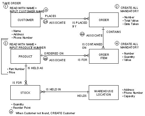
The Process Logic Diagram may not show details of repetitive and conditional actions, so important process logic questions may remain:
An optionality symbol can be used with a letter that identifies a note describing, for example, that the process should Read a certain entity only under certain circumstances, or what happens if, during the execution of the Take Order process. There is no customer associated with the customer Number requested.
For example, a list of product Part Numbers and order item Quantities serves as input to the Take Order process. The repetition bracket on the left of the illustration specifies that actions on product and order item should occur repeatedly.
These questions will be addressed more rigorously when building the Process Action Diagram.
Other actions you may identify during this step involve the use of common logic. These are formulated in CA Gen using action blocks that may be used by action diagrams for many processes and later in design by procedures. For example, part of the order item VALUE may be calculated using a Sales Tax algorithm.
Complete action diagrams should not normally need to be developed during analysis. There may be some circumstances when complex business logic needs to be captured, for example, business rules for calculating interest due. The ability of the data to support this can be verified by specifying information views and possibly by specifying an algorithm in note form. Otherwise, action diagrams should be detailed in design when developing the procedures and common action logic that will support them.
CA Gen creates an action diagram for every process that is designated elementary. Entity actions may be added during stereotyping, generated from expected effects or added by you. If no actions are added, the Check command will report an error. It will then be impossible for the designer to use the process until action details have been added.
For now, you can describe the process as part of the process definition, or as a set of notes in the Action Diagram for the process. Developing an action diagram is described in detail in the chapter "Block Mode Design" and the chapter "Client/Server Design."
You may now also define entity action views. At least one entity action view is required for each entity type participating in an entity action. Entity action views are discussed in defining Information Views. The phrase "participating in an entity action" is precise. Sometimes an entity type is only mentioned as part of the selection criteria for an entity of some other type. Regardless of this, an entity action view is required for it.
For example, a Read that finds any customer who placed an order for a certain product requires an entity action view for all four entity types (customer, order, order item, and product) even though attributes are only retrieved for customer. This is because these other entity types and relationships are needed to identify each customer.
|
Copyright © 2014 CA.
All rights reserved.
|
|