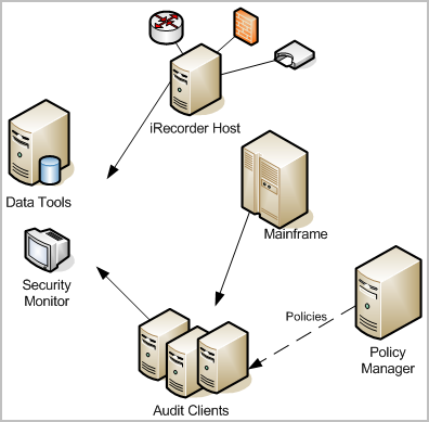

The following illustration shows a simplified CA Audit implementation:

In some enterprise deployments of CA Audit, event data is stored by the collector service in a relational database running on the Data Tools server. A database administrator monitors and maintains this database, and works with a system administrator to ensure that the correct policies are in place to gather desired events, and to exclude events that are not needed.
Solid lines in this diagram show events flowing from CA Audit clients, recorder, and iRecorder hosts to the Data Tools server, or in some cases to an optional security monitor console. A dashed line represents the control flow between the Policy Manager server and the clients using policies.
The Data Tools server provides basic reporting and visualization utilities as well as event storage. Custom queries and reports are the norm in enterprise implementations, and require significant time to create and to maintain.
This network topology allows for collection of a variety of event types from different devices, applications, and databases. You have central storage of collected events that is usually part of, or managed by, the Data Tools server which also offers some reports.
However, you need additional capabilities to scale your solution to handle rapidly increasing event volumes. You need to generate reports that demonstrate compliance with a variety of federal and international regulations. And you need to be able to find those reports quickly and easily.
|
Copyright © 2013 CA.
All rights reserved.
|
|