

|
|
|
The CA Unified Communications Monitor (UC Monitor) product has several features that make it uniquely capable of measuring echo levels in voice over IP telephone calls, sending alerts when echo crosses a threshold, and helping track down the source of an echo problem.
The UC Monitor system continually monitors both call setup performance and call quality on the VoIP network. ACOM is reported for all call legs that include a voice gateway. One of the default call quality threshold settings instructs the UC Monitor collector to raise alerts if ACOM values are too low. Like ERL, ACOM should be high. A UC Monitor alert is sent by default when ACOM drops to 15 dB. As stated earlier, ECANs use a limit of 6 dB to distinguish echo and avoid suppressing the actual contents of a conversation. If the ERL value is too low, the echo signal that returns to the gateway might be too loud, falling within 6 dB of the conversation signal. As a result, the ECAN treats the echo as voice and ignores it. With the default threshold settings, UC Monitor flags call quality as excessively bad when ACOM measurements, or the sum of ERL + ERLE, fall to 6 dB. ACOM measurements are available per gateway, so you can easily spot a gateway where excessive echo is causing call quality to deteriorate.
In addition to threshold monitoring, UC Monitor also reports ERL and ACOM values in real time for “watched” calls. The UC Monitor Call Watch feature collects additional diagnostic data from selected VoIP calls. During a Call Watch, the collector actively gathers detailed quality metrics for all calls made to and from a selected IP phone by polling the phone and any associated gateway, if a call to the PSTN is watched. The collected data is presented in a series of charts, which are displayed and updated in real time, as the watched calls are in progress.
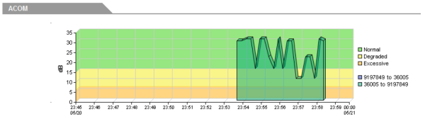
Figure 2. Real-time ACOM measurements are compared to the Degraded and Excessive performance thresholds.
The Call Watch report also includes Signal In and Signal Out metrics. In addition to contributing to the information gathering phase of troubleshooting a call-quality problem, these values can help engineers tune their echo cancelers. In order to tune the ECAN, test signals are introduced into a voice gateway circuit from an IP phone. Gain and attenuation are applied through the command line at the incoming and outgoing gateway interfaces until the desired values of ERL and ERLE are obtained.
Cisco System's typical echo testing procedures expect you to gather these metrics by frequently running a command from the command-line interface during an active phone call. Now you can simply start a UC Monitor Call Watch for a phone connected to the gateway under test, make a phone call to the PSTN to or from that phone, and take a look at the metrics as they are reported in real time. The signal levels are presented in a graph format that is continually updated during the tuning procedure.
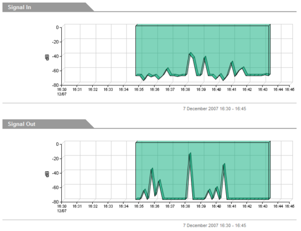
Figure 3. Signal In and Signal Out metrics are useful for tuning an echo canceller.
| Copyright © 2012 CA. All rights reserved. |
|