

The OneClick client application provides the graphical user interface to monitor the network and launch other client applications. Run the Discovery utility of OneClick to define and discover models that represent entities in the IT infrastructure.
The following diagram describes how to use Discovery:
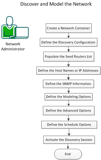
To discover and model the network, perform the following steps:
A container represents the group of devices that you want to model. Containers help you monitor and manage the health of the devices that they represent. Create a container in the Universe topology.
Follow these steps:
The <usxxyyzz> hierarchy identifies the local SpectroSERVER landscape.
Defines the unique host name for the device that you are modeling.
Specifies the IPv4 or IPv6 address for the device that lets CA Spectrum communicate with the device.
Specifies the security for the device. Adding a security string prevents certain users from viewing the model.
Specifies the device subnet address that the container represents. When specified, the subnet address label appears whenever a user points the mouse to a container icon in a topology view.
Discovery uses a set of configuration parameters that you can define to determine the network entities to discover and model.
Follow these steps:
The procedures that follow let you configure the parameters.
Note: The Seed Routers section is optional. We recommend that you populate the seed routers list for large Discovery operations.
Seed routers are a list of core routers that Discovery uses as a starting point when determining the routed subnets. All routers that are discovered within the IP / Host Name Boundary List are treated as seed routers. Add the seed routers list to let Discovery determine the routed subnets from the list.
Follow these steps:
Discovers the routing devices within the IP address range or host names.
Discovers the routed subnets within the IP range or host name.
Discovers the subnets that are routed by the routers that are discovered within the IP range or host name.
Scans the subnets that use ICMP or SNMP sweep. If you select this option, set the maximum subnet size in the counter.
Discovers the subnets that use the following tables:
Specifies that the subnet uses the Address Resolution Protocol (ARP) tables.
Specifies that the subnet uses the Cisco Discovery Protocol (CDP) tables.
The IP / Host Name Boundary List field populates with an IP range when you start Discovery with a container selected from the Topology tab. Import the host names, IP addresses, or IP address ranges from a file on the OneClick web server.
Follow these steps:
Microsoft Windows: C:\Program Files\Spectrum\IP_Files\core_network_ips
Solaris or Linux: /usr/Spectrum/IP_Files/core_network_ips
Import an ordered list of SNMP community strings for SNMP v1, SNMP v2c, or profiles for SNMP v3.
Follow these steps:
<name>v<SNMP_version>
Defines the SNMP community string.
Defines the applicable SNMP version.
Note: The version number for SNMPv1 community strings is optional.
public
public,v1
public,v2
public,v3
Define the modeling configuration settings to combine the Discovery and modeling sessions.
Follow these steps:
Discovery places all devices, including Layer 1 and Layer 2 in the Destination Container; no LAN containers are created.
Discovery places all Layer 3 devices, LAN containers, and Wide Area Links in the Destination Container. Layer 1 and Layer 2 devices are placed in the proper LAN container (based on IP address) under the Destination Container. If Discovery cannot find the appropriate LAN container for Layer 1 or Layer 2 devices, these devices are placed in the Destination Container.
Arranges the models in a grid pattern.
Arranges the models in a radial pattern.
Arranges the models in a tree structure.
Determines whether Discovery creates a WA_Link model between the wide area linked interfaces of two routers. When this option is disabled, Discovery directly connects the linked interfaces.
Determines whether Discovery uses a LAN container when representing an IP Subnet. Discovery creates the LAN container during the Layer 3 mapping process to connect a router to a local LAN.
Determines whether Discovery removes any empty LAN containers that the Create LANs (IP Subnets) option creates.
Determines whether Discovery models an 802.3 Fanout segment when CA Spectrum cannot make an accurate connection among three or more interfaces. This model represents the ambiguous connections among these interfaces. However, CA Spectrum uses network traffic data (IfInOctet and ifOutOctect statistics) when the Traffic Resolution protocol option is enabled. This protocol determines connections between interfaces and, in many cases, eliminates the need to model a Fanout.
Note: If you have 50 or more connections to a single Fanout model, consider changing the model to a Shared Media Link. The Shared Media Links must be modeled manually. These models can provide more control over fault management behavior when multiple connections are monitored. Unlike a Fanout model, Shared Media Links provide configurable thresholds for handling downstream connections that report problems. For example, a Fanout model reports a problem only when all downstream connections are down. However, a Shared Media Link can report the problem sooner, as when 60 percent of the downstream connections are down.
Determines whether to create a physical address model for a MAC address that a switch hears but not associates with any modeled device. The layer 2 mapper attempts to find a connection for each address found. If a connection is found, a Fanout is created and the physical address is associated to it through Connects_To. If no connection is found, the model is placed in Lost and Found.
Important! We recommend that you do not enable this option to avoid performance issues.
Determines whether CA Spectrum places the newly discovered devices directly into maintenance mode.
Determines the number of minutes that Discovery waits for new models to activate before mapping their connectivity. When the timeout expires without any new devices activating, connectivity is established to the possible extent. Connectivity occurs regardless of whether all connections to discovered devices have activated.
Limits: 5-15 minutes
Determines whether to use IP address tables when mapping. When disabled, Discovery disables Layer 3 mapping and maps only the Layer 2 connections. Additionally, Discovery disables the following options:
Determines whether to use the IP Address Table when mapping routers. By default, this option is not selected because these tables can be large and can take time to read. When this option is enabled, CA Spectrum cannot map unnumbered IP interfaces (0.0.0.0).
Determines whether Discovery uses the device Source Address table when mapping layer 2 connectivity.
Determines whether Discovery uses the Discovery Protocol tables when mapping device connectivity. Supported discovery protocols include Cisco, Nortel, Cabletron Switch, Extreme, Alcatel, Foundry, and Link Layer.
Determines whether Discovery uses the ARP table when determining MAC addresses that can be used for the connectivity mapping.
Determines whether Discovery uses the device Spanning Tree Address table (SAT) when mapping Layer 2 connectivity information about the device.
Determines whether Discovery uses network traffic data when determining connections between interfaces. In many cases, letting Discovery to use the traffic data eliminates the need to model Fanout segments.
Determines whether the ATM Discovery runs against all ATM switches in the SpectroSERVER database.
Note: For more information about ATM Protocols, see ATM Circuit Manager User Guide.
Note: OneClick displays the options that are based on the installed components.
Define Advanced Options to perform one of the following Discovery configuration procedures:
Follow these steps:
Uses ICMP when discovering devices. If ICMP is enabled, Discovery pings the devices in the ranges or subnets first. The devices that responded to ICMP are then queried using SNMP. This option reduces the number of SNMP requests, especially when multiple SNMP community strings are being used.
Identifies the neighbor routers and the routed subnets from the IP route tables. Use this option only if seed routers are specified in the Discovery configuration.
Staggers the processing workload of Discovery by pausing for one second after reading the routing table entries, if there are more than 1000 entries. Select High, Medium, or Low to pause after reading 50, 100, or 250 entries, respectively.
Specifies the number of seconds that Discovery waits for the response from a device.
Specifies the number of attempts that Discovery makes after the first attempt times out before establishing contact.
Specifies the payload size in bytes. This option is only available if you have selected ‘Use ICMP, then SNMP.’
Specifies the secured domain.
Note: This option is available only if you have the Secure Domain Manager installed. For more information, see the Secure Domain Manager User Guide.
Configure the scheduling options to run the configuration. If the configuration is scheduled, the schedule name is displayed in the Scheduling Options section.
Follow these steps:
Activate the Discovery session after defining all parameters.
Follow these steps:
The network is discovered and modeled.
The network entities and their connections are represented graphically in the Topology tab. Icons that are created, placed, and connected within the OneClick topology views represent various aspects of a modeled network.
This Documentation, which includes embedded help systems and electronically distributed materials, (hereinafter referred to as the “Documentation”) is for your informational purposes only and is subject to change or withdrawal by CA at any time. This Documentation is proprietary information of CA and may not be copied, transferred, reproduced, disclosed, modified or duplicated, in whole or in part, without the prior written consent of CA.
If you are a licensed user of the software product(s) addressed in the Documentation, you may print or otherwise make available a reasonable number of copies of the Documentation for internal use by you and your employees in connection with that software, provided that all CA copyright notices and legends are affixed to each reproduced copy.
The right to print or otherwise make available copies of the Documentation is limited to the period during which the applicable license for such software remains in full force and effect. Should the license terminate for any reason, it is your responsibility to certify in writing to CA that all copies and partial copies of the Documentation have been returned to CA or destroyed.
TO THE EXTENT PERMITTED BY APPLICABLE LAW, CA PROVIDES THIS DOCUMENTATION “AS IS” WITHOUT WARRANTY OF ANY KIND, INCLUDING WITHOUT LIMITATION, ANY IMPLIED WARRANTIES OF MERCHANTABILITY, FITNESS FOR A PARTICULAR PURPOSE, OR NONINFRINGEMENT. IN NO EVENT WILL CA BE LIABLE TO YOU OR ANY THIRD PARTY FOR ANY LOSS OR DAMAGE, DIRECT OR INDIRECT, FROM THE USE OF THIS DOCUMENTATION, INCLUDING WITHOUT LIMITATION, LOST PROFITS, LOST INVESTMENT, BUSINESS INTERRUPTION, GOODWILL, OR LOST DATA, EVEN IF CA IS EXPRESSLY ADVISED IN ADVANCE OF THE POSSIBILITY OF SUCH LOSS OR DAMAGE.
The use of any software product referenced in the Documentation is governed by the applicable license agreement and such license agreement is not modified in any way by the terms of this notice.
The manufacturer of this Documentation is CA.
Provided with “Restricted Rights.” Use, duplication or disclosure by the United States Government is subject to the restrictions set forth in FAR Sections 12.212, 52.227-14, and 52.227-19(c)(1) - (2) and DFARS Section 252.227-7014(b)(3), as applicable, or their successors.
Copyright © 2014 CA. All rights reserved. All trademarks, trade names, service marks, and logos referenced herein belong to their respective companies.
|
Copyright © 2014 CA.
All rights reserved.
|
|