

Federation Guides › Federation in Your Enterprise › Legacy Federation Process Flow
Legacy Federation Process Flow
This section contains the following topics:
Flow Diagram for SSO Using SAML 1.x Artifact Authentication
Flow Diagram for SSO Using SAML 1.x POST Profile Authentication
Flow Diagram for SSO Using SAML 2.0 Authentication with Artifact Binding
Flow Diagram for SSO Using SAML 2.0 Authentication with POST Binding
Flow Diagram for WS-Federation SSO Initiated at the Resource Partner
Flow Diagram for SAML 2.0 Single Logout
Flow Diagram for WS-Federation Signout (AP-initiated)
Flow Diagram for WS-Federation Signout (RP-initiated)
Flow Diagram for Identity Provider Discovery Profile
Flow Diagram for SSO Using SAML 1.x Artifact Authentication
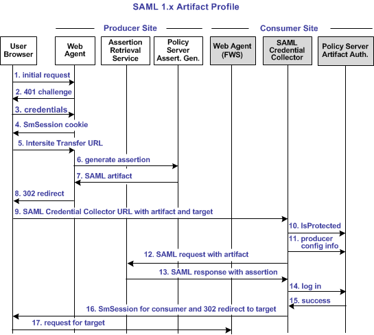
The following illustration shows the flow between a user and the legacy federation components at the producer and consumer sites. This set-up enables single sign-on between the sites. SAML artifact profile is the authentication method and the flow diagram assumes successful authentication and authorization at the producer and consumer sites.
Note: This flow applies to examples that do not use the SAML Affiliate Agent.
The process flow diagram for SAML 1.x Artifact Authentication follows.
Note: The SPS federation gateway can replace the Web Agent and Web Agent Option Pack to provide the Federation Web Services application functions. In the flow diagram, the Web Agent block would be the embedded Web Agent in the SPS federation gateway. For information about installing and configuring the SPS federation gateway, see the Secure Proxy Server Administration Guide.
The sequence of actions is as follows:
- The user makes an initial request to a protected page at the producer site.
- The Web Agent at the producer site responds with a 401 challenge to the user.
- The user submits credentials, such as the user name and password to the Web Agent.
- The Web Agent issues a CA SiteMinder® SMSESSION cookie to the browser of the user for the producer site domain.
- The user clicks a link to visit the consumer site. This link is referred to as the intersite transfer URL because it results in transferring the user to another site. The intersite transfer URL makes a request to the Web Agent at the producer site first. This URL contains the location of the SAML credential collector and the target URL to access at the consumer site.
- The Web Agent at the producer site handles the intersite transfer URL request by calling the assertion generator.
- The assertion generator generates a SAML assertion, places it in the session store and returns the SAML artifact for the assertion.
- The Web Agent responds with a 302 redirect to the SAML credential collector at the consumer. The redirect contains the SAML artifact and the target URL as query parameters.
- The browser makes a request to the URL for the SAML credential collector at the consumer site.
- The SAML credential collector handles the URL request by making an isProtected call to the SAML artifact authentication scheme.
- The SAML artifact authentication scheme returns the producer configuration information.
- The SAML credential collector uses the producer configuration information to make a SAML request to the assertion retrieval service at the producer. In this step, the SAML credential collector is acting as an HTTP client.
- The assertion retrieval service at the producer retrieves the SAML assertion from the session store. The service responds with a SAML response that contains the SAML assertion.
- The SAML credential collector makes a login call to the SAML artifact authentication scheme, passing the SAML assertion as credentials.
- The SAML artifact authentication scheme validates the SAML assertion. The authentication scheme looks up the user record. The lookup is based on the user mapping that is configured for the scheme. The scheme returns a success reply. If the SAML assertion is not valid or a user record cannot be located, the scheme returns a failure reply.
- If the scheme returns a success reply, the SAML credential collector issues a CA SiteMinder® SMSESSION cookie for the consumer domain to the browser. The SAML credential collector also issues a 302 redirect to the target URL. If the scheme returns a failure reply, the SAML credential collector issue a 302 redirect to a no access URL.
- The browser makes a request to the target URL at the consumer, which the Web Agent protects.
Flow Diagram for SSO Using SAML 1.x POST Profile Authentication
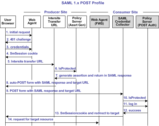
The following illustration shows the detailed flow between a user and the components at producer and consumer sites. This set-up enables single sign-on between the sites. SAML POST profile is the authentication method and the illustration assumes successful authentication and authorization at the producer and consumer sites.
Note: This flow applies to examples that do not use the SAML Affiliate Agent.
The process flow diagram for SAML 1.x POST Profile follows.
Note: The SPS federation gateway can replace the Web Agent and Web Agent Option Pack to provide the Federation Web Services application functions. In the flow diagram, the Web Agent block would be the embedded Web Agent in the SPS federation gateway. For information about installing and configuring the SPS federation gateway, see the Secure Proxy Server Administration Guide.
The sequence of events is as follows:
- User requests a local page at the producer, which the Web Agent protects.
- The Web Agent at the producer asks for user credentials.
This flow diagram assumes that the resource is protected with basic authentication and that user name and password are the required credentials.
- The user submits credentials.
- The Agent at the producer issues an SMSESSION cookie for the producer site domain and allows access to the local page.
- The user selects a link at the local page of the producer to visit the consumer. The link looks like it goes to the consumer site, but it goes to the intersite transfer URL. The URL contains the affiliate name, the assertion consumer URL, and the target resource as query parameters.
- The Intersite Transfer Service makes an IsProtected call to the Policy Server for the resource. The URL contains the name query parameter that uniquely identifies the consumer.
- The Policy Server recognizes the request as a request for a SAML assertion. The Policy Server generates the assertion and returns it in a digitally signed SAML response message. The Policy Server then returns the response to the intersite transfer URL.
- The intersite transfer URL service generates an auto-POST form containing the encoded SAML response and the target URL as form variables. The service sends the form to the browser.
- The browser of the user automatically posts the HTML form to the SAML Credential Collector at the consumer site. This URL is read from the SAML response that the intersite transfer URL service sends.
- The Credential Collector makes an isProtected call to the SAML POST profile authentication scheme. The authentication scheme informs the assertion consumer what type of credentials are required.
- The Credential collector makes a login call for the requested target resource to the SAML POST profile authentication scheme, passing the assertion as credentials.
- If the login succeeds, the SAML Credential Collector generates an SMSESSION cookie for the consumer site domain.
- The SMSESSION cookie is placed in the browser and redirects the user to the target resource.
- The browser requests the target resource, which the consumer-side Web Agent protects. The browser has an SMSESSION cookie for the consumer domain so the Web Agent does not challenge the user.
Flow Diagram for SSO Using SAML 2.0 Authentication with Artifact Binding
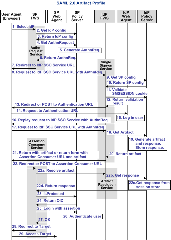
The following illustration shows the detailed flow between a user and the components at the Identity Provider and Service Provider. This set-up enables single sign-on between the sites and uses the SAML 2.0 authentication scheme with the artifact binding as the authentication method.
The flow diagram assumes the following information:
- The SP initiates the request for a resource.
- Successful authentication and authorization at the IdP and SP sites.
Note: This flow applies to examples that do not use the SAML Affiliate Agent.
The flow diagram for SAML 2.0 Authentication-Artifact Binding follows.
Note: The SPS federation gateway can replace the Web Agent and Web Agent Option Pack to provide the Federation Web Services application functions. In the flow diagram, the Web Agent block would be the embedded Web Agent in the SPS federation gateway. For information about installing and configuring the SPS federation gateway, see the Secure Proxy Server Administration Guide.
The sequence of events is as follows:
- The user chooses a link at the SP to authenticate at a specific IdP. This link must include a Provider ID representing the chosen IdP.
- SP FWS requests the IdP configuration information from the local Policy Server.
- The local Policy Server returns the IdP configuration information to SP FWS. FWS can cache the configuration information.
- SP FWS requests an AuthnRequest message from the local Policy Server through a tunnel call, passing the Provider ID. This call must contain the artifact profile in the ProtocolBinding element value.
- The local Policy Server generates the AuthnRequest message in an HTTP redirect binding.
- The local Policy Server returns the AuthnRequest message to the SP FWS in an HTTP redirect binding.
- SP FWS redirects the user to the IdP SSO Service URL. FWS obtains the configuration information and includes it in the AuthnRequest message in an HTTP redirect binding.
- The browser requests the IdP single sign-on service (SSO) URL.
- IdP FWS requests the SP configuration information from the IdP local Policy Server.
- The local Policy Server returns the configuration information.
Note: FWS can cache the configuration information.
- IdP FWS gets an SMSESSION cookie for the domain of this IdP and calls the Policy Server to validate it. If there is no SMSESSION cookie, the IDP FWS skips redirects or posts to the Authentication URL.
- The Policy Server verifies the validity of the SMSESSION cookie and returns the result.
- If the SMSESSION cookie does not exist or is not valid, the IDP FWS redirects or posts to the Authentication URL. If the SMSESSION cookie is valid, the IDP FWS requests a SAML 2.0 artifact from the local Policy Server (see step 18).
- The browser requests the Authentication URL, which the IdP Web Agent protects.
- The IdP Web Agent logs the user in, setting the SMSESSION cookie, and lets the request pass to the Authentication URL.
- The Authentication URL is the redirect.jsp file, which replays the request to the IdP single sign-on service with the AuthnRequest message.
- The browser requests the IdP single sign-on service URL. This request is equivalent to the request from step 8, but now the user has a valid SMSESSION cookie.
- The IdP FWS requests a SAML 2.0 artifact from the local Policy Server. FWS passes the AuthnRequest through an authorization call to the realm obtained from the configuration information.
- The Policy Server generates the artifact and the corresponding response message. The message is formed from the configuration information from the Service Provider. The Policy Server stores the response in the session store.
The message is stored as a session variable, and is named using the string representation of the artifact message handle.
- The Policy Server returns the artifact to IdP FWS.
- Based on the SP configuration information, the IdP FWS takes one of the following actions:
Note: The assertion generator can indicate that the authentication level for the current session is too low. If the level is too low, the IdP FWS redirects to the authentication URL to facilitate step-up authentication.
- If the artifact was sent as part of a URL, the browser redirects the user to the Assertion Consumer URL with the artifact. If the artifact was returned in a form, then the browser POSTs the artifact to the Assertion Consumer URL.
The following steps reflect the back-channel call that the SP FWS Assertion Consumer service makes to the IdP FWS Artifact Resolution Service to resolve the artifact into a response message.
- The SP FWS obtains the artifact from the GET or POST data, depending on how the IdP FWS is configured to redirect the browser. FWS then obtains the SOAP endpoint of the Artifact Resolution Service from the IdP configuration information. The source ID is part of the artifact. After the SOAP endpoint is obtained, the SP FWS makes a back-channel call to the IdP FWS Artifact Resolution service to resolve the artifact.
- The IdP FWS requests the response message from the local Policy Server. The message that is stored as a session variable is requested using the Java Agent API. The session ID is extracted from the artifact. The session variable name is the string representation of the artifact message handle.
- The local Policy Server retrieves the response message from the session store and deletes it after the artifact retrieval.
- The local Policy Server returns the response message to the IdP FWS. The IdP FWS returns the response message to the SP FWS Assertion Consumer Service.
The back-channel call is now complete.
- The SP FWS obtains the response message from the post data. The service then determines the target resource from the configuration and makes an isProtected call to the Policy Server for the target resource.
If the assertion is encrypted, the FWS makes a tunnel call. This call takes the encrypted assertion and returns the assertion in the clear.
- The Policy Server returns the realm OID for the target resource.
- The SP FWS passes the response message to the local Policy Server through a login call. The response message acts as the credentials and the realm OID is obtained from the isProtected call.
- The SAML 2.0 authentication scheme logs the user in using the response message as credentials.
- The local Policy Server returns OK to the SP FWS.
- If a success reply is returned, SP FWS creates an SMSESSION cookie for the SP domain. The service places the cookie in the browser and redirects the user to the target URL, which is obtained from the configuration information.
If the login fails, the SP FWS redirects the user to a No Access URL.
- The browser of the user requests the target URL, which the SP-side Web Agent protects. Because the browser has an SMSESSION cookie, the Web Agent does not challenge the user.
Flow Diagram for SSO Using SAML 2.0 Authentication with POST Binding
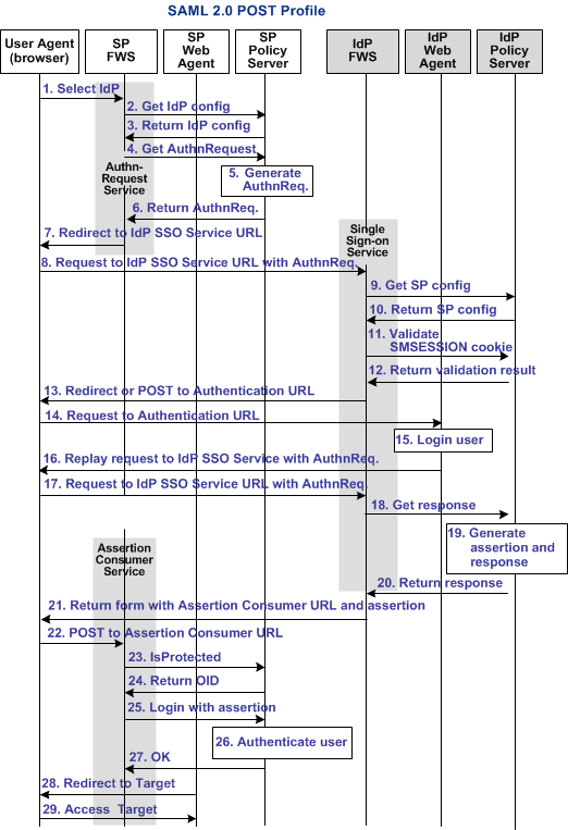
The following illustration shows the detailed flow between a user and the components deployed at an Identity Provider (IdP) and Service Provider (SP) sites. This set-up enables single sign-on between the sites, using SAML 2.0 POST binding as the method of obtaining the SAML assertion for authentication.
The flow diagram assumes the following:
- The SP initiates the request for a resource.
- Successful authentication and authorization at the IdP and SP sites.
Note: This flow applies to examples that do not use the SAML Affiliate Agent.
The flow diagram for SAML 2.0 authentication-POST binding follows.
Note: The SPS federation gateway can replace the Web Agent and Web Agent Option Pack to provide the Federation Web Services application functions. In the flow diagram, the Web Agent block would be the embedded Web Agent in the SPS federation gateway. For information about installing and configuring the SPS federation gateway, see the Secure Proxy Server Administration Guide.
The sequence of events is as follows:
- The user chooses a link at the SP to authenticate at a specific IdP. This link must include a Provider ID representing the chosen IdP.
- SP FWS requests the IdP configuration information from the local Policy Server.
- The Policy Server returns the IdP configuration information to SP FWS. FWS can cache this configuration information.
- SP FWS requests an AuthnRequest message from the local Policy Server through a tunnel call, passing the Provider ID.
- The Policy Server generates the AuthnRequest message in an HTTP redirect binding.
- The local Policy Server returns the AuthnRequest message to the SP FWS in an HTTP redirect binding.
- SP FWS redirects the user to the IdP Single Sign-on Service URL, which is obtained from the configuration information with the AuthnRequest message.
- The browser requests the IdP Single Sign-on Service URL.
- IdP FWS requests the SP configuration information from the IdP local Policy Server.
- The local Policy Server returns the configuration information.
Note: FWS can cache the configuration information.
- IdP FWS gets an SMSESSION cookie for this domain of the IdP and calls the Policy Server to validate it. If there is no SMSESSION cookie, the IDP FWS redirects or posts to the Authentication URL.
- The Policy Server verifies the validity of the SMSESSION cookie and returns the result.
- If the SMSESSION cookie does not exist or is not valid, the IDP FWS redirects or posts to the Authentication URL. FWS obtains this URL from the configuration information. If the SMSESSION cookie is valid, the IDP FWS skips to 18.
- The browser requests the Authentication URL, which the IdP Web Agent protects.
- The IdP Web Agent logs the user in, setting the SMSESSION cookie and lets the request pass to the Authentication URL.
- The Authentication URL is the redirect.jsp file, which replays the request to the IdP single sign-on service with the AuthnRequest message.
- The browser requests the IdP single sign-on service URL. This request is equivalent to the request from step 8, but now the user has a valid SMSESSION cookie.
- The IdP FWS requests a SAML 2.0 assertion from the Policy Server. The AuthnRequest goes through an authorize call to the realm obtained from the configuration information.
- The Policy Server generates an assertion that is based on the configuration information for the SP, signs it, and returns the assertion wrapped in a response message.
- The response message is returned to IdP FWS.
- IdP FWS returns a form to the user. The form contains the response message, the Assertion Consumer URL, obtained from the configuration information, and the JavaScript to submit the form.
Note: If the assertion generator indicates that the current sessions authentication level too low, the IdP FWS redirects to the authentication URL as in Step 13 to facilitate step-up authentication.
- The browser posts the response message to the Assertion Consumer URL at the SP.
- The SP FWS obtains the response message from the POST data. FWS then determines the target resource from the configuration and makes an isProtected call to the Policy Server for the target resource.
If the assertion is encrypted, the FWS makes a tunnel call. The call takes the encrypted assertion and returns the assertion in the clear.
- The Policy Server returns the realm OID for the target resource.
- The SP FWS passes the response message to the local Policy Server through a login call. FWS uses the response message as credentials and the realm OID obtained from the isProtected call.
- The SAML 2.0 authentication scheme logs the user in using the response message as credentials.
- The local Policy Server returns OK to the SP FWS.
- If a success reply is returned, SP FWS creates an SMSESSION cookie for the SP domain. FWS then places the cookie in the browser and redirects the user to the target URL, which is obtained from the configuration information.
If the login fails, the SP FWS redirects the user to a No Access URL.
- The browser sends a request to the target URL, which the SP-side Web Agent protects. Because the browser has an SMSESSION cookie, the Web Agent does not challenge the user.
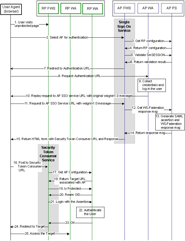
Flow Diagram for WS-Federation SSO Initiated at the Resource Partner
The following illustration shows the detailed flow between a user and the legacy federation components at an Account Partner (AP) and Resource Partner (RP) sites. This set-up enables single sign-on between the sites, using WS-Federation as the method of obtaining the SAML assertion for authentication.
The flow diagram assumes the following information
- The Resource Partner initiates the request for a resource.
- Successful authentication and authorization at the AP and RP sites.
Note: The SPS federation gateway can replace the Web Agent and Web Agent Option Pack to provide the Federation Web Services application functions. In the flow diagram, the Web Agent block would be the embedded Web Agent in the SPS federation gateway. For information about installing and configuring the SPS federation gateway, see the Secure Proxy Server Administration Guide.
The WS-Federation single sign-on process is as follows:
- The user visits an unprotected site selection page at the Resource Partner.
- The user chooses a link to authenticate for AP that is a federated partner. This link points to the Single Sign-on Service at the AP. The link must contain the Provider ID of the RP and can include some optional parameters, such as the wctx parameter. The browser requests the AP SSO Service URL.
- Based on RP provider ID specified as a query parameter, the AP FWS requests the RP configuration information from the local Policy Server.
- The local Policy Server returns the configuration information.
Note: The FWS can cache the configuration information.
- The AP FWS gets the SMSESSION cookie for the AP domain and calls the Policy Server to validate it. If there is no SMSESSION cookie, the AP FWS skips to step 7.
- The Policy Server verifies the validity of the SMSESSION cookie and returns the result to the FWS application.
- If the SMSESSION cookie does not exist or is not valid, the AP FWS redirects the user to the Authentication URL obtained from the RP configuration information. If the SMSESSION cookie is valid, the AP FWS skips to step 12.
- The browser requests the Authentication URL, which the AP Web Agent protects.
- The AP WA authenticates the user and sets the SMSESSION cookie. The AP WA lets the request pass to the Authentication URL.
- The Authentication URL points to the redirect.jsp, which replays the request to the AP SSO service with the original wsignin message.
- The browser requests the AP SSO Service URL. This request is equivalent to the request from step 2, but now the user has a valid SMSESSION cookie.
- The AP FWS requests a WS-Federation <RequestSecurityTokenResponse> from the Policy Server through an authorize call to the realm obtained from the configuration information.
- The Policy Server generates a SAML1.1 assertion that is based on the configuration information for the RP. The Policy Server signs the assertion and returns it wrapped in an <RequestSecurityTokenResponse> message.
- The <RequestSecurityTokenResponse> message is returned to the AP FWS.
- The AP FWS returns a form to the user containing the following information:
- URL encoded <RequestSecurityTokenResponse> message.
- Security Token Consumer Service URL.
- Optional wctx that came with the wsignin message.
- JavaScript to auto submit the form.
If the original wsignin request contains the wreply parameter, its value becomes the Security Token Consumer URL. The wreply value becomes the URL only if the Security Token Consumer URL setting is not in the RP configuration information. For security reasons, the Security Token Consumer URL setting in the RP configuration information takes precedence over the wreply parameter.
Note: The assertion generator can indicate that the authentication level of the current session is too low. If the level is too low, the AP FWS redirects to the authentication URL as in step 7 to facilitate “step-up” authentication.
- The user agent posts the <RequestSecurityTokenResponse> message and wctx to the Security Token Consumer URL at the RP.
- The RP FWS obtains the <RequestSecurityTokenResponse> message and wctx from the POST data. RP FWS requests the AP configuration information from the local Policy Server.
- RP FWS determines the target resource from the AP configuration information from local Policy Server. If the target resource is not part of the AP configuration, and the wctx parameter is found in the POST data, the wctx value becomes the target resource.
- FWS makes an isProtected call to the Policy Server for the target resource.
- The Policy Server returns the realm OID for the target resource.
- The RP FWS passes the <RequestSecurityTokenResponse> message to the local Policy Server through a login call. The <RequestSecurityTokenResponse> message and the realm OID obtained from the isProtected call service as credentials.
- The WS-Federation authentication scheme logs the user in using the <RequestSecurityTokenResponse> message as credentials.
- The local Policy Server returns an OK status message to the RP FWS.
- The RP FWS creates the SMSESSION cookie for the RP domain. FWS places the cookie in the browser and redirects the user to the Target URL or to the wctx POST data. If the login fails, the RP FWS redirects the user to a No Access URL.
- The user agent requests the Target URL that the RP-side Web Agent protects. Because the browser has the SMSESSION cookie for the RP domain, the Web Agent does not have to challenge the user.
WS-Federation SSO Initiated at the Account Partner
Single sign-on that is initiated by the Account Partner is similar to the RP-initiated use case. HTML content at AP contains intersite transfer links to different RP sites. When the user clicks any link, the web browser requests the AP SSO Service URL. The rest of the processing is same as specified in the RP-initiated use case.
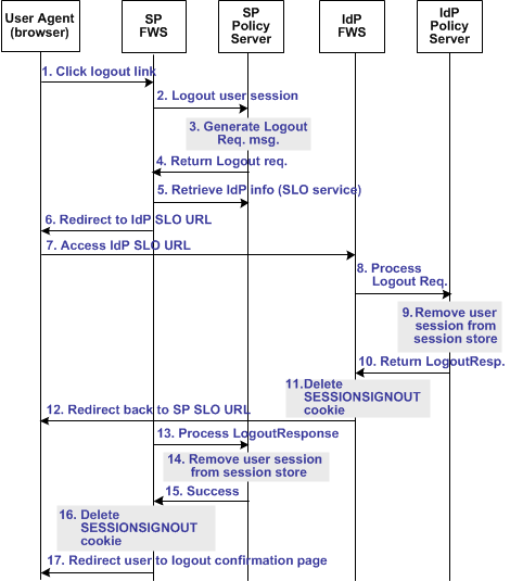
Flow Diagram for SAML 2.0 Single Logout
The following illustration shows the detailed flow for a single logout request between a user and the legacy federation components at an Identity Provider (IdP) and Service Provider (SP). This set-up enables single logout for all entities that have a session with a particular user.
The following illustration assumes that the SP initiates the log out request.
Note: The SPS federation gateway can replace the Web Agent and Web Agent Option Pack, which provide the FWS application functions. For more information about installing and configuring the SPS federation gateway, see the CA SiteMinder Secure Proxy Server Administration Guide.
The sequence of events is as follows:
- The user clicks a link at SP to end the global session. The browser of the user accesses the Single Logout servlet at the SP.
SP FWS renames the SMSESSION cookie to SESSIONSIGNOUT to invalidate the current session of the user.
- FWS reads the SessionId value from the SESSIONSIGNOUT cookie and asks the Policy Server to terminate the user session.
- Based on the session store information, the user session status is changed to a LogoutInProgress state in the session store. The Policy Server determines that the user session is created based on the SAML assertion received from an IdP. The Policy Server generates a LogoutRequest request to invalidate the user session at the IdP.
- The Policy Server returns a LogoutRequest request to SP FWS. The Policy Server also returns the Provider ID of the IdP and provider type.
- SP FWS retrieves the provider configuration data of the IdP, which includes the SLO service URL, from the Policy Server.
- SP FWS redirects the user to the SLO service at the IdP with the SAML LogoutRequest message added as a query parameter.
- The browser of the user accesses SLO service at the IdP.
When the IdP FWS receives a LogoutRequest message, it renames the SMSESSION cookie to SESSIONSIGNOUT.
- The IdP processes the signed LogoutRequest message. The IdP then tries to invalidate the user session at all SPs specified in the session store for that session. The only SP that is not invalidated is the SP that sent the original LogoutRequest.
Note: The process for logging the user out at each SP is similar to Step 2 through Step 7.
- After terminating the user session from all relevant SPs, the IdP removes the user session from the session store.
- The IdP Policy Server returns a signed LogoutResponse message to the IdP FWS, containing the provider ID of the SP and provider type. The IdP Policy Server also informs FWS that the user session is removed from the session store.
- After learning that the user session is removed from the session store, IdP FWS deletes the SESSIONSIGNOUT cookie.
- The IdP FWS redirects the user to the single logout service at the SP with the SAML LogoutResponse message added as a query parameter. The single logout service is part of the SP FWS application.
The browser of the user accesses SLO service of the SP, which processes the signed LogoutResponse message.
If the LogoutResponse message contains non-SUCCESS return code, FWS issues a SIGNOUTFAILURE cookie, and a base 64-encoded Partner ID is appended to the cookie value. If there are multiple IDs in the cookie, a space character separates them.
- The SP Policy Server receives the LogoutResponse message from FWS and processes it.
- The SP Policy Server removes the user session from the session store.
- After the session is removed from the session store, the Policy Server sends a SUCCESS return code to FWS. The Policy Server includes the SP ID in the final LogoutResponse message.
- If there are no more LogoutRequest or LogoutResponse messages to process, SP FWS deletes the SESSIONSIGNOUT cookie.
- FWS redirects the user to the Logout Confirmation page at the SP.
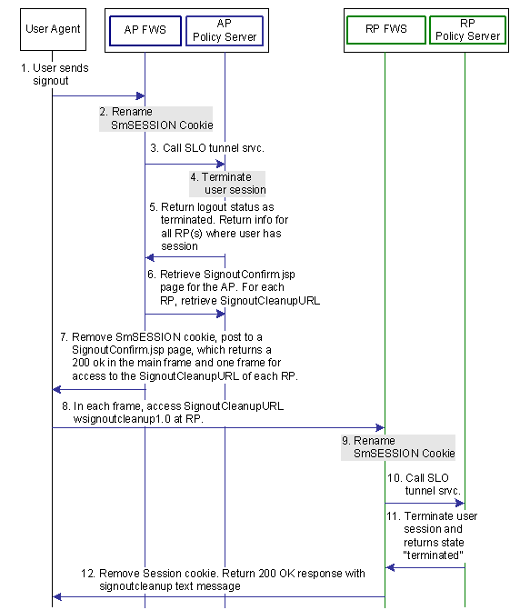
Flow Diagram for WS-Federation Signout (AP-initiated)
The following illustration shows the flow for a signout request between a user and the legacy federation components deployed at an Account Partner (AP) and Resource Partner. This set-up enables signout for all entities that have a session with a particular user.
The following illustration assumes that the AP initiates the signout request.
Note: The SPS federation gateway can replace the Web Agent and Web Agent Option Pack, which provide the FWS application functions. For more information about installing and configuring the SPS federation gateway, see the CA SiteMinder Secure Proxy Server Administration Guide.
When signout is initiated at the Account Partner, the process flow is as follows:
- The user clicks on a link at the Account Partner to end the global session. The browser of the user sends a HTTP-based wsignout request to the signout servlet at the Account Partner.
- FWS renames the SMSESSION cookie to SESSIONSIGNOUT to invalidate the current session of the user.
- FWS reads the SessionId value from the SESSIONSIGNOUT cookie and calls the SLO Tunnel Service API to terminate the user session from the session store.
- The SLO Tunnel Service API sets the user session status to "Terminated" in the session store. The service also removes all the RP references from the session store that are associated with that user session.
- The SLO Tunnel Service API returns the logout status "Terminated" to the FWS Signout Servlet. The Tunnel library also returns the RP providerID and providerType for all the RPs associated with the user session.
- FWS retrieves the provider configuration data of the RP, which includes the signout cleanup URL, from the cache of the provider maintained in FWS.
- FWS removes the SESSIONSIGNOUT cookie then posts an AP Signout message and multiple RP-SignoutCleanup locations as post data to the SignoutConfirmURL JSP. The SignoutConfirmURL JSP is responsible for parsing various post variables and creating a frame-based HTML page. The mainframe in this HTML page displays the AP-SignOut message. Each of the remaining frames accesses the SignoutCleanupURL of individual RPs associated with the user session.
- The browser of the user accesses SignoutCleanup service at the Resource Partner site in an individual frame.
- When the RP FWS (Signout Servlet) receives a wsignoutcleanup request, it renames the SMSESSION cookie to SESSIONSIGNOUT. FWS then calls the SLO Tunnel Service API to process the wsignoutcleanup request.
- The SLO tunnel library processes the wsignoutcleanup request and terminates the user session from the session store.
- Then SLO tunnel library returns FWS with a "Terminated" status message indicating that the user session no longer exists in the session store.
- The FWS Signout Servlet removes the SESSIONSIGNOUT cookie and returns a 200 OK response in the frame.
Note: Steps 8-12 are repeated for individual RPs simultaneously in different frames of the same HTML page.
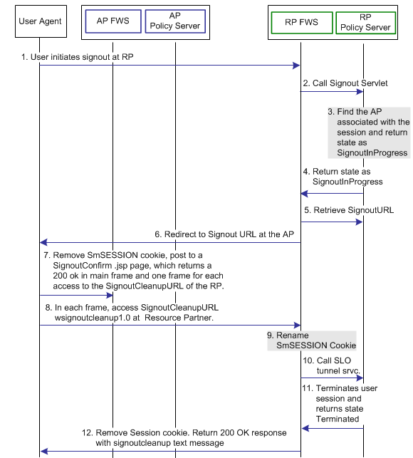
Flow Diagram for WS-Federation Signout (RP-initiated)
The following illustration shows the flow for a signout request between a user and the legacy federation components at an Account Partner (AP) and Resource Partner. This set-up enables signout for all entities that have a session with a particular user.
The following illustration assumes that the RP initiates the sign out request.
Note: The SPS federation gateway can replace the Web Agent and Web Agent Option Pack, which provide the FWS application functions. For more information about installing and configuring the SPS federation gateway, see the CA SiteMinder Secure Proxy Server Administration Guide.
When signout is initiated at the Resource Partner, the process flow is as follows:
- The user clicks a link at the Resource Partner to end the global session. The browser sends a HTTP-based wsignout request to the Signout servlet at the Resource Partner.
Note: The RP site is receiving a wsignout message and not a wsignoutcleanup message.
- FWS reads the SessionId value from the SMSESSION cookie, renames the SMSESSION cookie to SESSIONSIGNOUT, and calls the SLO tunnel library with the wsignout request.
- Based on information in the session store, the tunnel library determines determines the AP associated with the user session. The SLO tunnel library sets the user session state to SignoutInProgress, but does not terminate it.
- The tunnel library returns the SignoutInProgress state message and the Account Partner providerID and providerType.
- FWS retrieves Account Partner configuration data, which includes the Signout URL, from the FWS cache or Policy Server.
- FWS redirects the browser of the user to the Signout URL.
- FWS removes the SESSIONSIGNOUT cookie then posts an AP signout message and multiple RP-SignoutCleanup locations as post data to the SignoutConfirmURL JSP. The SignoutConfirmURL JSP is responsible for parsing various post variables and creating a frame-based HTML page. The primary frame in this HTML page displays the AP-SignOut message. Each of the remaining frames accesses the SignoutCleanupURL of individual RPs associated with the user session.
- The browser accesses SignoutCleanup service at the Resource Partner site in an individual frame.
- When RP FWS (Signout Servlet) receives a wsignoutcleanup request, it renames the SMSESSION cookie to SESSIONSIGNOUT. The service then calls the SLO Tunnel Service API to process the wsignoutcleanup request.
- The SLO tunnel library processes the wsignoutcleanup request and terminates the user session from the session store.
- Then SLO tunnel library returns FWS with a Terminated status message indicating that the user session no longer exists in the session store.
- The FWS Signout Servlet removes the SESSIONSIGNOUT cookie and returns a 200 OK response in the frame.
Note: Steps 8-12 are repeated for individual RPs simultaneously in different frames of the same HTML page.
Flow Diagram for Identity Provider Discovery Profile
The following illustration shows the flow for an Identity Provider Discovery service between the user and the legacy federation components at an Identity Provider. This set-up involves redirecting from an Identity Provider to the Identity Provider Discovery Profile service to set the common domain cookie.
The following illustration assumes that the SP FWS redirects the user to the IdP SSO Service URL.
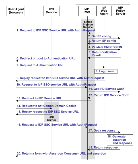
Note: The SPS federation gateway can replace the Web Agent and Web Agent Option Pack to provide the Federation Web Services application functions. In the flow diagram, the Web Agent block would be the embedded Web Agent in the SPS federation gateway. For information about installing and configuring the SPS federation gateway, see the Secure Proxy Server Administration Guide.
The Identity Provider Discovery process is as follows:
- The user agent (browser) requests the IdP SSO Service URL.
- The IdP FWS requests the SP configuration information from the local Policy Server.
- The local Policy Server returns the configuration information.
Note: The FWS can cache the configuration information.
- The IdP FWS gets the SMSESSION cookie for the IdP domain and calls to the Policy Server to validate it. If there is no SMSESSION cookie, the IdP FWS skips to Step 6.
- The Policy Server verifies the validity of the SMSESSION cookie and returns the result.
- If the SMSESSION cookie does not exist or is not valid, the IdP FWS redirects or posts to the Authentication URL obtained from the configuration. If the SMSESSION cookie is valid, the IdP FWS skips to Step 18.
- The user agent requests the Authentication URL. The IdP Web Agent protects the Authentication URL.
- The IdP Web Agent logs the user in, setting the SMSESSION cookie and lets the request pass to the Authentication URL.
- The Authentication URL is the redirect.jsp file, which replays the request to the IdP SSO Service with the AuthnRequest message.
- The user agent requests the IdP SSO Service URL. This request is equivalent to the request from step 8, but now the user has a valid SMSESSION cookie.
- The IdP FWS requests the Identity Provider Discovery Profile (IPD) configuration from the Policy Server, passing the Identity Provider ID.
- The Policy Server returns with the IPD configuration, such as IPD Service URL, common domain cookie, and persistence information of the common domain cookie.
- The IdP FWS redirects the user to the IPD Service URL to set the common domain cookie.
- The IdP FWS redirects the user to the IPD Service URL.
- The IPD Service sets or updates the common domain cookie with the Identity Provider ID. The IPD Service redirects the user agent back to the IdP FWS from which it received the Set Request.
- The user agent requests the IdP SSO Service URL.
- The IdP FWS requests a SAML 2.0 assertion from the Policy Server, passing the AuthnRequest through an authorize call to the realm obtained from the configuration.
- The Policy Server generates an assertion that is based on the configuration information for the Service Provider. The Policy Server signs the assertion and returns the assertion wrapped in a response message.
- The response message is returned to the IdP FWS.
- The IdP FWS returns a form to the user containing the response message, the Assertion Consumer URL obtained from the configuration and Javascript to submit the form.
Note: The assertion generator can indicate that the authentication level of the current session is too low. If the level is too low, the IdP FWS redirects to the authentication URL as in Step 13 to facilitate step-up authentication.
After the final step in the diagram, the user agent posts the response message to the Assertion Consumer URL at the Service Provider.
Copyright © 2015 CA Technologies.
All rights reserved.
|
|