

|
|
|
NTS-SI lets SAW data and session data collected in one domain be passed on to another NTS running in another domain, provided that a direct ISR link exists.
Suppose that session B1-B2 exists between two resources, B1 and B2, in domain B. For the NTS in domain A to be aware of SAW and session data for this session, the following conditions must be true:
Provided that these conditions are met, a session start notification received by NTS B from VTAM B is forwarded across the ISR link to NTS A. If any session data arrives for session B1-B2 from VTAM B, NTS B forwards an indication to NTS A that this data is available. Users of NTS A can solicit this data, as required, from NTS B. When the session ends, a session end notification received by NTS B from VTAM B is forwarded to NTS A. NTS A performs end-of-session processing for this session according to the session class definition.
The following illustration shows this process.
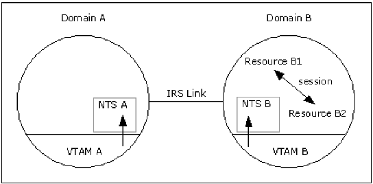
Note the following in this illustration:
In a cross-domain environment (single network), NTS forwards data it has received from the local VTAM to other NTS regions. SAW and session data received using ISR from a remote VTAM are not forwarded, shown in the following illustration.
In this illustration, NTS B has information for sessions in domains A and B. NTS B forwards data relating to sessions in domain B to NTS C, but does not forward data relating to sessions in domain A. Therefore, when constructing a network image, NTS C cannot include SAW and session data from domain A.
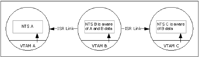
Note the following in this illustration:
For single network image presentation, the most useful configuration of NTS regions is a star network, which enables the monitoring of network activity to be centralized (or distributed). The following illustration shows an optimum NTS-SI configuration for a five-domain network (arrows indicate the flow of data).
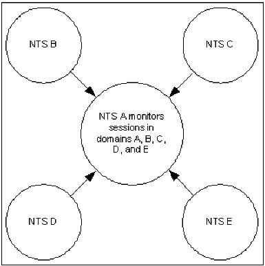
The central (hub) NTS region monitors all network activity in its own domain and in the outlying (spoke) domains; the spoke NTS regions monitor the activity in their own domains only. This configuration parallels the Communication Management Configuration (CMC), where a hub domain owns all the devices and the applications reside in the spoke domains.
| Copyright © 2012 CA. All rights reserved. |
|