

|
|
|
CA Plex supports many types of diagrams (including diagram types that you can make yourself), but this tutorial only shows you how to create an Entity Attributes diagram.
In the diagram you create in this chapter, you:
To create an Entity Attributes diagram
Project described by Project Diagram
This creates the diagram object. Remember, you can drag the Project entity from the Object Browser to the Model Editor, rather than typing it in manually.
![]()
The diagram opens with the Select Diagram Type dialog on top:
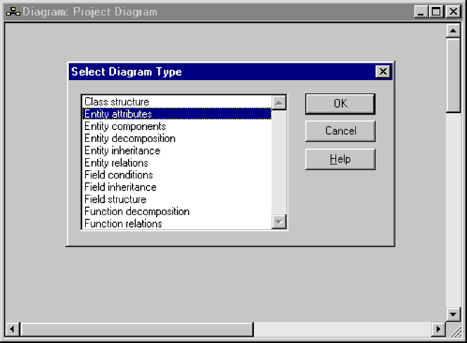
You can now work in the diagram you just created. A diagram is like a canvas, on which you put nodes, sub-nodes, and links between nodes, to represent your data model.
![]()
Notice that the diagram creates a node for the Project entity. Also notice that it has an asterisk (*) after the name:
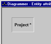
The asterisk indicates that the object has attributes that the diagram can show.
Next, you will change a diagram setting so that it shows the attributes of all entities represented by it.
![]()
The diagram now displays the attributes you defined for the Project entity in the chapter “Defining Entities.”
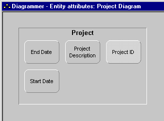
Notice that the node automatically resized to show all of its attributes.
The Project ID sub‑node has a lighter color to indicate that it is a key. You will see later in this chapter how the Diagrammer uses display characteristics to indicate foreign keys and other special attributes.
| Copyright © 2012 CA. All rights reserved. | Tell Technical Publications how we can improve this information |