

|
|
|
In this section, you define two relationships between entities: an owned by, and a refers to relationship.
In your application, a task is part of a project. Therefore, if you delete a project, you want all of its tasks to be deleted. Because of this, you define Project as the owner of Task, so that each task is directly related to the project it is part of. This is known as an owned by relationship, which is sometimes referred to as a parent‑child relationship.
When you define a task that is part of a project, this project management application requires that you specify an employee who is responsible for completing the task. Because an employee can be assigned to more than one task, in more than one project, you do not want to delete the employee record if you delete a task. So, you define a refers to relationship between the Task and Employee entities.
When you add the triple Task refers to Employee, the Task entity stores the identifier of the Employee entity, and uses it as a pointer to that entity. The stored value is called a foreign key.
An employee can be assigned to more than one task, even to more than one task in more than one project, but a task can have only one employee assigned to it.
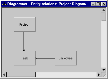
To define relationships in a diagram:
This creates an owned by relationship between the two entities. Next, you create a refers to relationship between Task and Employee.
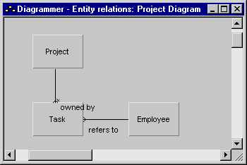
The diagram should look something like this:
You can see the relationships between the entities, but the links look the same, with no indication of what kinds of relationships they represent. Next, you change the display so that it shows more information.
| Copyright © 2012 CA. All rights reserved. | Tell Technical Publications how we can improve this information |