

|
|
|
You define an SNA group by entering data on the following panels:
To define an SNA group
The SNA Group General Description panel appears.
Press F1 (Help) for more information about the fields.
The SNA group is saved.
Use the SNA Group General Description panel to specify the name, the operation mode, and the description of the group.
Use a meaningful name to identify the SNA group, for example, DUBBOBRANCH. A meaningful name helps you identify the groups when you monitor the groups from the status monitor. The name must contain alphanumeric, @, #, and $ characters only, but must not start with a digit. The name can be up to twelve characters long.
You can categorize the SNA groups by type. The SNA Group Type field defines a pseudo class name that is displayed on the status monitor instead of the actual SNA group class name. The default is SNAGROUP.
Specify an operation mode of AUTOMATED, IGNORED, MANUAL, or OFF in the Operation Mode field. During operation, the specified mode can be restricted by the global operation mode, which is specified in the AUTOIDS parameter group.
You can attach an availability map using the Availability Map field, which defines the changes to the normal availability of the SNA group.
Leave the Map Name field blank if you want to use the default desired state, which can be either ACTIVE or INACTIVE (as set in the AUTOIDS parameter group during region initialization).
Note: You can create a new map from the group definition. You can name a new map and define it, or access an existing map, change the name, and update the copy. The map is created in the knowledge base when you save the definition.
Use the SNA Group Filters panel to define the criteria that select the members of the SNA group.
Use the Resource Name, the Resource Type, and the Filter Name fields in any combination to define the selection criteria. You can specify up to 97 independent lines of criteria. For each line, you also specify a weighting to indicate how important the selected resources are to the group.
Specify the SNA resource name selection criterion in the Resource Name field. The following two types of generic indicators are available:
You cannot mix the two types of indicators.
The wildcard characters that you can use in the Resource Name field are as follows:
The asterisk (*) is also a valid wildcard character. It behaves the same way as the _ character when embedded and as the % character at other positions. For example, * and NM* are valid values.
Downstream and upstream indicators denote whether resources below and above a named resource are to be selected as members. The indicators are as follows:
Selects the next level of downstream resources only.
Selects all downstream resources.
Selects the next level of upstream resources only.
Selects all upstream resources.
The following criteria are valid examples: <PU1, <PU1>, and <<PU1>.
Important! When you monitor an SNA group, the group discovers all its members and monitors them. If you are using a >> downstream indicator and a resource becomes available downstream at a later time, the group will not discover it and the resource will not affect the status of the group. To restore such a resource, you can use the BLD or BLDALL command.
Specify the SNA resource type selection criterion in the Resource Type field. The default value is an asterisk (*), indicating all types.
If you use a downstream or an upstream indicator in the Resource Name field, you can only use the default value in the Resource Type field. You can, however, use a filter to set the type criterion.
You can use a predefined SNA group filter to incorporate more advanced selection criteria. Name the filter in the Filter Name field.
An SNA group filter enables you to select resources that:
SNA group filters are similar to the SNA resource filters that you use to customize your view of SNA resources.
You can use the U (Update Filter) action code to modify a specified filter. You can use the L (List Filters) action code to access the list of defined filters. From the list panel, you can create new filters. The filters use Boolean operators to specify the selection criteria.
Usually, a filter applies to all SNA resources selected by the criteria in the Resource Name and Resource Type fields. However, if a >> downstream indicator is used, filtering occurs level by level instead. That is, if no resources that satisfy the filter criteria are found at the next lower level of a branch, filter processing stops.
Example: >> Downstream Indicator
You use the >> downstream indicator to display resources downstream to SNALINE1.
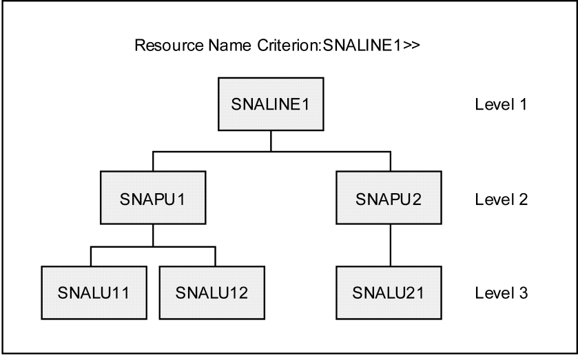
Depending on other criteria, the filter gives the following results:
|
If the filter looks for resources of the … |
Then … |
|
LU type (RSTYPE=“LU”) |
No resources are selected because no LUs are found on level 2. |
|
PU type (RSTYPE=“PU”) |
SNAPU1 and SNAPU2 are selected. |
The weight indicates how important a member is to the SNA group. The valid values are 0% through 100%.
You can apply the following two types of weights to the members: fixed and proportional.
With a fixed weight, every member included in a line entry has the weight specified in the Weight field.
You cannot use a fixed weight if downstream or upstream indicators are used in the selection criteria on that line.
In the following two examples, the weight is 100% fixed:
You can use the proportional type of weight when the line entry includes more than one member. With a proportional weight, the apportionment of weight to the selected members depends on whether downstream or upstream indicators are used in the selection criteria. The following diagram provides examples of apportionment of a proportional weight.
The selection criteria select the members for the SNA group. Only members included in the SNA network model are selected. Therefore, the members can change if the filter used by the network model changes. The network model filter is set in the AUTOSNACNTL region customization parameter group.
Note: For more information about the parameter group, see the Installation Guide.
You can use the V (View) action to display the members selected by the criteria specified on a line. When a downstream indicator is used, only SNA resources one level down from the selected member are displayed. You can, however, explore further by selectively displaying the resources downstream to a member.
The State Thresholds panel defines how the states of the members affect the actual state and, optionally, logical state of the SNA group.
The actual state of the group can be one of the following: UNKNOWN, FAILED, DEGRADED, STOPPING, INACTIVE, STARTING, and ACTIVE.
The state threshold is set by the specified combined weight of the members that have particular states. The region checks the states in the sequence UNKNOWN to ACTIVE until a threshold is found to be equaled or exceeded. That is, if the UNKNOWN state threshold requirement is satisfied, the group takes on the UNKNOWN state irrespective of whether the other threshold requirements are satisfied. If none of the threshold requirements are satisfied, the group takes on the DEGRADED state.
If an SNA resource selection line on the SNA Group Filters panel finds no members, its weight is added to the combined weight for the UNKNOWN state.
The combined weight of the members also affects the logical state of the SNA group. When a logical state threshold percentage is specified, the region compares the desired state with the actual state of each SNA resource in the SNA group to determine their logical states. The combination of these logical states determines whether the SNA group logical state is OK or not OK. The logical state of the SNA group is then derived.
Note: When a logical state threshold is specified and there is a resource whose desired state is different from the group desired state, automation is not performed on this resource if it is in a logical state of OK.
The mapping of these special logical states is in the SNA Resource Logical State Normalization table (one of the display attribute tables). To access the list of tables, enter /ASADMIN.A.
The weight contributions to an SNA group state depend on whether any downstream or upstream indicators are used in the SNA resource name criterion.
If downstream or upstream indicators are not used, the weight applied to selected members can be either fixed or proportional. In the following example:
The weight contributions are as follows:
|
If the weight is … |
Then the contribution to the group state is … |
|---|---|
|
Fixed |
60% ACTIVE and 30% INACTIVE |
|
Proportional |
20% ACTIVE and 10% INACTIVE |
If upstream indicators are used, the weight applied to selected members must be proportional. The weight is equally distributed between the members. In the following example:
The weight contributions are 50% ACTIVE and 50% INACTIVE.
If downstream indicators are used, the weight applied to selected members must be proportional. The following illustration shows how member states contribute to the status of the SNA group. It shows an example of members selected by using a downstream indicator.
In the following illustration, the resource name criterion is SNALINE1>>, and the weight is 100% proportional.
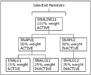
In this illustration, the contributions to the group state are as follows:
The lowest level of SNA resources only contributes to the determination of the state of the SNA group at any single branch.
Example: Indicators
An SNA group contains 10 SNA lines. You want the state of the group to indicate the conditions in the following table:
|
State |
Description |
|---|---|
|
UNKNOWN |
The region does not know the state of one or more lines. |
|
FAILED |
One or more lines failed. |
|
DEGRADED |
One or more lines degraded. |
|
STOPPING |
One or more lines are stopping. |
|
INACTIVE |
All lines are INACTIVE. |
|
STARTING |
One or more lines are starting. |
|
ACTIVE |
All lines are active. |
|
DEGRADED |
The member states do not satisfy any of the above conditions. For example, five lines are active and five lines are inactive. |
You define a 100% proportional weighting distributed across the lines. That is, each line has a weight of 10%.
Note: If you use downstream indicators in the selection criteria, the downstream SNA resources affect the group state. Therefore, one line means 10% of the lines, where the contributions to a group state might come from part of a line.
The following table shows the state thresholds that satisfy your requirements:
|
Actual State |
Threshold |
|
UNKNOWN |
10% |
|
FAILED |
10% |
|
DEGRADED |
10% |
|
STOPPING |
10% |
|
INACTIVE |
100% |
|
STARTING |
10% |
|
ACTIVE |
100% |
The State Change Exits panel lets you specify the following types of exit processes:
The logical state of an SNA group is normally determined using the Automated or Manual Mode Attributes Table (/ASADMIN.A). You can more accurately determine the logical state of an SNA group by specifying a Logical State Threshold on the State Thresholds panel. This threshold determines, from the combined logical state of each resource, whether the SNA group is OK or not OK. If the group is OK, then conceptually the actual state of the SNA group is said to match its desired state. If the group is not OK, then conceptually the actual state of the SNA group is said to be in a state (ACTIVE or INACTIVE) that is different from its desired state. These states are compared to the Automated or Manual Mode Attributes Table to determine the SNA group’s logical state.
Example: SNA Group Logical State
Assume you have specified 10% as the logical state threshold for the SNA group as specified in the previous example.
The actual state of one SNA line is FAILED, desired ACTIVE. Using the specified actual state thresholds, the actual state of the SNA group is FAILED. Because a logical state threshold is specified, the logical state of the SNA group is determined using the following method:
---- Automation Services : SNA Resource Logical State Normalization Table -----
Command ===>                                                    Function=BROWSE


                     .-----------+---------------------.
                     |   SNA     |    SNA RESOURCE     |
                     | RESOURCE  |    DESIRED STATE    |
                     |  ACTUAL   +----------+----------+
                     |  STATE    | ACTIVE   | INACTIVE |
                     +---------------------------------+
                     | ACTIVE    | OK       | NOTOK    |
                     | STARTING  | OK       | NOTOK    |
                     | STOPPING  | NOTOK    | OK       |
                     | DEGRADED  | OK       | NOTOK    |
                     | INACTIVE  | NOTOK    | OK       |
                     | FAILED    | NOTOK    | NOTOK    |
                     | UNKNOWN   | NOTOK    | NOTOK    |
                     '-----------+----------+----------'
The Actual state of the resource (FAILED) is compared to the desired state of the resource (ACTIVE) to determine the logical state of the resource (NOTOK). In this case, the logical state is not OK.
Note: If the SNA group is OK, then conceptually it is known as ACTIVE by the region.
The Automation Log Details panel contains information about the size of the temporary log for the SNA group (called a transient log), the destination of the logged information, and the type of information logged.
The Owner Details panel lets you identify up to two people who can be contacted if this SNA group has operational problems.
The Extended Function Exit panel lets you provide additional operator functions. Specify the exit NCL procedure that provides these functions. The procedure is invoked when an operator issues the XF command against the SNA group.
The extended function exit NCL procedure has access to variables with the prefix ZRM or ZRS.
| Copyright © 2012 CA. All rights reserved. |
|