

|
|
|
The CTCPATH statement identifies the CTC device addresses used to transport the VCF from the master system to the client systems. This statement is valid only when selecting the CTCONLY or CTCDASD communication methods.
Conceptually, a CTC device connects an I/O address on one processor to an I/O address on another processor. VCF data that is sent from one side is received on the other side, so every transmission consists of two operations: an outbound write operation from one side, and an inbound read operation on the other side. Data may be transmitted in either direction over a CTC path, but it travels in only one direction at any one moment.
The following information describes how to implement the CTCPATH statement:
The CTCPATH statement has the following parameters:
The ADDRESS parameter defines the CTC device addresses used to communicate in an outbound fashion from the system indicated in the FROMSYSTEM parameter. At least one primary address must be specified. The alternate addresses are used in recovery situations.
Identifies the originating system for the path. This system sends the VCF in an outbound fashion on this path.
Identifies the destination system for the path. This system receives the VCF in an inbound fashion on this path.
Examples
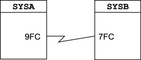
CTCPATH FROMSYSTEM=SYSA ADDRESS=9FC TOSYSTEM=SYSB
CTCPATH FROMSYSTEM=SYSB ADDRESS=7FC TOSYSTEM=SYSA
You would place the preceding CTCPATH statements in the MIMINIT member to represent this configuration.
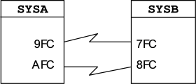
CTCPATH FROMSYSTEM=SYSA ADDRESS=(9FC,AFC) TOSYSTEM=SYSB
CTCPATH FROMSYSTEM=SYSB ADDRESS=(7FC,8FC) TOSYSTEM=SYSA
You would place the previous CTCPATH statements in the MIMINIT member to represent this configuration.
In this example, 9FC/7FC is the primary path, and AFC/8FC is the alternate path. The alternate path is used only when a problem is detected with the primary path. Alternate paths do not provide any performance advantages in terms of load sharing. They are for backup purposes only. Up to 15 alternate paths can be defined between any two systems. The total number of CTCPATH statements required for your site depends on the number of systems defined in the MIMplex, and whether you want a symmetrical or an asymmetrical configuration. We recommend symmetrical configurations because full redundancy provides the best recovery options. Master system recoverability is particularly important in CTCONLY environments.
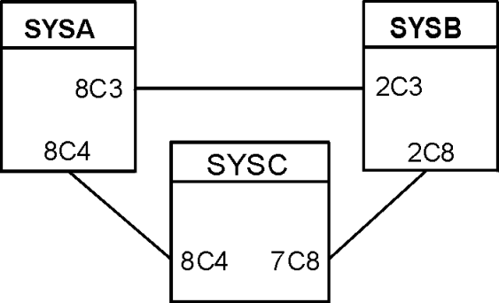
CTCPATH FROMSYSTEM=SYSA ADDRESS=8C3 TOSYSTEM=SYSB
CTCPATH FROMSYSTEM=SYSB ADDRESS=2C3 TOSYSTEM=SYSA
CTCPATH FROMSYSTEM=SYSB ADDRESS=2C8 TOSYSTEM=SYSC
CTCPATH FROMSYSTEM=SYSC ADDRESS=7C8 TOSYSTEM=SYSB
CTCPATH FROMSYSTEM=SYSC ADDRESS=8C4 TOSYSTEM=SYSA
CTCPATH FROMSYSTEM=SYSA ADDRESS=8C4 TOSYSTEM=SYSC
You would place the preceding CTCPATH statements in the MIMINIT member to represent this configuration.
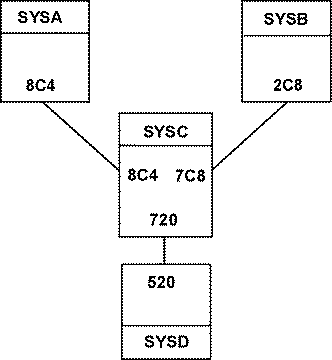
CTCPATH FROMSYSTEM=SYSA ADDRRSS=8C4 TOSYSTEM=SYSC
CTCPATH FROMSYSTEM=SYSC ADDRRSS=8C4 TOSYSTEM=SYSA
CTCPATH FROMSYSTEM=SYSB ADDRRSS=2C8 TOSYSTEM=SYSC
CTCPATH FROMSYSTEM=SYSC ADDRRSS=7C8 TOSYSTEM=SYSB
CTCPATH FROMSYSTEM=SYSD ADDRRSS=520 TOSYSTEM=SYSC
CTCPATH FROMSYSTEM=SYSC ADDRRSS=720 TOSYSTEM=SYSD
The preceding CTCPATH statements are placed in the MIMINIT member to represent this configuration.
Virtual Control File Sizing Considerations
If the CA MIM complex is executing in a mixed CTC and DASD control file environment, then the size of the virtual control file (VCF) image is a mirror image of the primary backup DASD control file. The VCF image contains exactly the same number of blocks (of size MIMINIT BLKSIZE), as the primary backup DASD control file. The primary backup DASD control file is defined as the DASD control file that was in use when the migration to the VCF took place. CA MIM supports up to 100 DASD control files, and we recommend that alternate DASD control files be progressively larger in size than the primary control file. When the primary DASD control file or the VCF becomes full, a migration to a larger alternate DASD control file is successful. The larger alternate DASD control file yields an equally larger size VCF when compared to the original DASD control file size.
When running in a VCF-only environment (that is, MIMINIT COMMUNICATION=CTCONLY or MIMINIT COMMUNICATION=XCF), the size of the Virtual Control File image is dynamic. The MIMINIT BLKSIZE specification multiplied by the MIMINIT VCFMAXBLOCKS specification determines the initial VCF size. When the VCF image needs to be increased in size, the detecting system expands the VCF dynamically. As each external system accesses the VCF, the system detects that the VCF has been expanded and begins operating with the increased file size. Depending upon the MIMINIT BLKSIZE specification, the VCF image can expand to a maximum of 2 gigabytes.
| Copyright © 2011 CA. All rights reserved. | Tell Technical Publications how we can improve this information |