

Example 2 shows how the user changed the print characters used to draw the data structure diagram. This example also illustrates the INCLUDE statement by representing only the areas that the user specified instead of representing the entire schema or subschema. (See Exhibit 5.Exhibit 4.e print characters were changed--The user knew that the default characters used to draw the left and right arrows in the diagram, the less-than ( < ) and greater-than ( > ) symbols, were not on the user's print chain. In addition, the user wanted to experiment with the characters used to draw record blocks, set connections, and indexes.
Why specific areas were selected--Instead of representing the entire schema or subschema by the diagram, the user needed only the areas specified to be represented in the diagram for a particular application. The INCLUDE statement produced a diagram that represents only the areas the user selected.
Parameters Entered--In this case, the user wrote PROCESS, CHARDEF, and INCLUDE statements from scratch to a Parameter Statements File (see Exhibit 4.1).
 PROCESS=SUBSCHEMA, SCHEMA=DSRR1016, VERSION=1, SUBSCHEMA=DBRR1016,
     DICTNAME=TKIT

     OPTIONS,COMPRESS=ON

     CHARDEF,RHORCHAR==,RVERCHAR=;,SLLCHAR=L,SLRCHAR=J,
         SULCHAR=F,SURCHAR=7,LARROW=C,RARROW=D,ISLACHAR=X

     INCLUDE AREA STUDENT-REGION
     INCLUDE AREA CLASS-REGION
Exhibit 4.6: Example 2--Parameters Entered
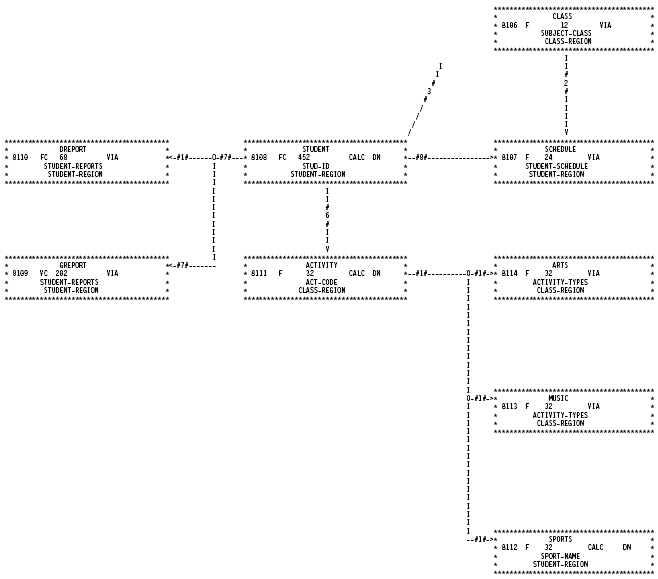
Exhibit 4.7: Tailored CA IDMS Schema Mapper Data Structure Diagram with User-Specified Characters and Areas
|
Copyright © 2013 CA.
All rights reserved.
|
|