
In the logical design process, you represented relationships between entities with diamonds and identified the keys associated with the relationship.
During the previous step ("Representing Entities") you changed each many-to-many relationship to two one-to-many relationships by creating a new entity. All relationships between entities should now fall into only two categories:
Representing the relationships
To represent the relationships in the preliminary data structure diagram, perform the following steps:
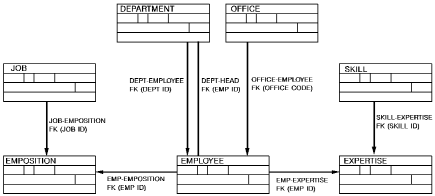
For example, the relationship between OFFICE and EMPLOYEE could be called OFFICE-EMPLOYEE and the relationship between SKILL and EXPERTISE could be called SKILL-EXPERTISE.
The foreign key will be shown as part of the definition of the relationship.
Foreign keys in a one-to-many relationship
In a one-to-many relationship, the key of the one entity is carried as a foreign key in the many entity.
For example, in the relationship between the entities OFFICE and EMPLOYEE, the key for the OFFICE entity (the one entity) is carried as a foreign key in the EMPLOYEE entity (the many entity).
Add the foreign key to the list of data elements associated with the appropriate entity and indicate each foreign key on the data structure diagram, as described below:
For example, specify OFFICE CODE under the OFFICE-EMPLOYEE relationship to indicate that the data element OFFICE CODE is a foreign key for that relationship.
To avoid having two data elements with the same name (EMP ID) as keys to the entity, assign unique names to the foreign keys. For example, you might name the keys MGR ID and EMP ID to distinguish managers from workers.
Note: The foreign key in a self-referencing relationship must be nullable. If it were not nullable, the first piece of data stored could not satisfy the referential integrity of the relationship. For example, the first employee stored would carry a manager ID that would not match an existing employee ID, as the integrity of the relationship requires. If the self-referencing relationship carries data, that data must also be nullable.
Foreign keys in a one-to-one relationship
In a one-to-one relationship, the foreign key can be placed in either entity participating in the relationship. Usually, you can conserve space by placing the foreign key in one of the two entities. For example, if there is a relationship between DEPARTMENT and EMPLOYEE to indicate which employee is head of a department, you can conserve space by placing the EMP ID of the head of the department in the DEPARTMENT entity rather than the other way around since there will typically be far more employees than departments.
Diagramming relationships between entities
The diagram below shows a portion of the data structure diagram for Commonweather after your changes have been made.

|
Copyright © 2014 CA.
All rights reserved.
|
|