

Each PCB statement must be followed by a SEGMENT statement for each DL/I segment participating in the DL/I hierarchy. Each SEGMENT statement relates a DL/I segment to a CA IDMS/DB segment to an/ record; the run-time interface uses the CA IDMS/DB record name to represent the segment. The SEGMENT statement also defines relationships between the named segment and other DL/I segments, as represented by the corresponding CA IDMS/DB records and set relationships.
To review SEGMENT statements, you need to locate the relevant PSB and the DBD specified in the DL/I PCB that corresponds to this PCB. If the specified DBD defines a logical DBD, you must also find the accompanying DBDs that define the physical databases and the index databases. Similarly, if the PCB calls for a HIDAM database or for a database with a secondary index, you must locate the DBDs that define the associated index databases. Additionally, you must have a copy of the relevant CA IDMS/DB schema.
There must be a SEGMENT statement for each segment specified in a SENSEG statement in the DL/I PCB. If the processing options A or D have been entered in the PROCESSING OPTION clause of the PCB statement, you may have to enter more SEGMENT statements to identify the dependent segments. The decision on whether additional segments must be identified in a separate SEGMENT statement can be made only after looking at the accompanying DBD and, optionally, a hierarchy diagram of the DBD. Note if any segment defined in the accompanying DBD is a dependent of a segment that is specified in a SENSEG statement. You must define each of these dependent segments with a separate SEGMENT statement if the segment identified in the SEGM statement can be deleted.
SEGMENT statements must appear in hierarchical order. The first SEGMENT statement under a given PCB statement must identify the root segment for the hierarchy. All subsequent SEGMENT statements must be included in the order in which the segments appear in the hierarchy. Similarly, if the DBD specified in the PCB defines a logical database, the SEGMENT statements must appear in the same order as the segments appear in the logical hierarchy. A logical DBD can create inversions from a secondary index and/or from a logical relationship. In such cases, consider the following:
The SEGMENT statements must be included to define the segments participating in the logical relationship inversion in reverse hierarchical order. Therefore, the SEGMENT statement defining the destination parent segment must be the first SEGMENT statement in the inversion, and the SEGMENT statement defining the root segment in the destination parent segment's physical database must be the last segment statement in the inversion. Always include the SEGMENT statements for the segments in the logical relationship inversion even if the segments are neither identified in the PCB nor defined in the logical DBD. In such cases, you can assign the segments a status of NOT SENSITIVE. (See the discussion of the USE clause below.)
You must also include SEGMENT statements for each of these segments even if some of them are defined in other SEGMENT statements for the named DBD. If the same segment is included in the logical inversion and is specified in the named DBD, make sure that the segment's name is different each time it is specified in a SEGMENT statement for the named PCB. If the name is the same in both the logical and physical DBD, change the segment name in the SEGMENT statement that is part of the logical inversion. Use instead any name you choose.
Syntax
►►─── SEGMent name is dl1-segment-name ──────────────────────────────────────►

 ►─── RECORD name is idms-record-name ───────────────────────────────────────►

 ►─┬──────────────────────────────┬──────────────────────────────────────────►
   └─ PARENT is dl1-segment-name ─┘

 ►─┬──────────────────────────┬──────────────────────────────────────────────►
   └─ thru SET idms-set-name ─┘

 ►─┬─────────────┬───┬────────────┬──────────────────────────────────────────►
   ├─ PARENT ◄───┤   └─ is OWNER ─┘
   └─ CHILD ─────┘

 ►─┬──────────────┬───┬──────────────────────────────────────────┬───────────►
   ├─ PHYSical ◄──┤   └─ DESTination PARENT is idms-record-name ─┘
   └─ LOGical ────┘
 ►─┬──────────────────────────┬──────────────────────────────────────────────►
   └─ thru SET idms-set-name ─┘

 ►─┬──────────────────────────────────────────────────────────────────────┬──►
   └─ INSERT RULES are ─┬─ Logical ◄──┬─,─┬ Logical ◄──┬─,─┬─ Logical ◄─┬─┘
                        ├─ Physical ──┤   ├ Physical ──┤   ├─ Physical ─┤
                        └─ Virtual ───┘   └ Virtual ───┘   └─ Virtual ──┘

 ►─┬───────────────────────────────────────────────────────────────────────┬─►
   └─ REPLACE RULES are ─┬─ Logical ◄──┬─,─┬ Logical ◄──┬─,─┬─ Logical ◄──┬┘
                         ├─ Physical ──┤   ├ Physical ──┤   ├─ Physical ──┤
                         └─ Virtual ───┘   └ Virtual ───┘   └─ Virtual ───┘

 ►─┬─────────────────────────────────────────────────────────────────────────►─
   └─ ACCESS METHOD is ─── HDAM ─────────────────────────────────────────────
─►───────────────────────────────────────────────────────────────┬───────────►
  ─┬───────────────────────────────────────────────────────────┬─┘
   ├─ HIDAM PROCessing SEQuence INDEX is indexed-field-name ───┤
   └─ HISAM PROCessing SEQuence SET is indexed-set-name ───────┘

 ►─┬─────────────────────────────────────────┬───────────────────────────────►
   └─ SEQuence is by LOGical sequence field ─┘

 ►─┬───────────────────────────────────────────────────┬─────────────────────►◄
   └─ USE is ─┬─ NOT SENsitive ───────────────┬── . ───┘
              ├─ VIRTual LOGical CHILD (VLC) ─┤
              ├─ KEY ─────────────────────────┤
              ├─ DATA ◄───────────────────────┤
              ├─ KEY,KEY ─────────────────────┤
              ├─ KEY,DATA ────────────────────┤
              ├─ DATA,KEY ────────────────────┤
              └─ DATA,DATA ───────────────────┘
Parameters
Identifies a DL/I segment that participates in the hierarchy being defined. Dl1-segment-name must be a 1- to 8-character name. Make sure that each dl1-segment-name is used only once within the named DBD.
Identifies the CA IDMS/DB record corresponding to the segment named in the SEGMENT NAME clause. Idms-record-name must be the 1- to 16-character name of a record included in the subschema named in the IPSB SECTION and in the RECORD SECTION. For all segments but those in logical databases, the record named here corresponds directly to the segment named in the SEGMENT NAME clause.
When a segment participating in a logical database is named, use the record corresponding to the segment named in the first entry of the SEGM statement's SOURCE parameter. For concatenated segments, which are found only in logical databases, use the record corresponding to the real logical child segment. If the logical child specified in the concatenated segment is the virtual logical child segment, you must first locate the SEGM statement defining the virtual logical child segment to identify the name of the real logical child segment. (For more information, see DL/I and CA IDMS/DB.)
Identifies the parent of the segment named in the SEGMENT NAME clause. The PARENT IS clause must be included for all child segments (that is, segments other than root segments). Dl1-segment-name must be a 1- to 8-character segment name and must be the name of a DL/I segment specified in the SEGMENT NAME clause of a preceding SEGMENT statement in the hierarchy.
When entering segments from the database referred to by the PCB, the entry for the PARENT IS clause is the first value in the PARENT parameter of the SEGM statement defining the child segment. Omit this entry, however, when the SEGMENT statement defines a root segment. When entering the SEGMENT statements that define the segments in a logical relationship inversion, the entry for the PARENT IS clause is the name of the SEGMENT defined in the preceding SEGMENT statement. For example, if the destination parent segment is SEGA, and the next segment in the hierarchical path of the destination parent segment in its physical database is SEGB, SEGA is the entry in the SEGMENT statement for SEGB. This entry is correct even though the SEGM statement defining SEGA in its physical DBD shows SEGB as the parent of SEGA.
Identifies the CA IDMS/DB set that relates the child and parent segments named in the SEGMENT NAME and PARENT IS clauses. The THRU SET clause must be included when the PARENT NAME clause is present. Idms-set-name must be a 1- to 16-character set name and must be included in the subschema named in the IPSB SECTION.
Identifies the owner of the parent/child set. The default is PARENT.
Identifies the CA IDMS/DB record representing the destination parent in a concatenated segment structure. Include this clause only if the record identified in the RECORD NAME clause corresponds to a logical child segment in a logical database.
LOGICAL DESTINATION PARENT must be specified if the logical child named in the DL/I SOURCE parameter of the SEGM statement defining the concatenated segment is the real logical child segment. PHYSICAL DESTINATION PARENT must be specified if the logical child named in the DL/I SOURCE parameter of the SEGM statement defining the concatenated segment is the virtual logical child segment.
Idms-record-name is the CA IDMS/DB record corresponding to the logical child entry in the concatenated segment. This operand must be a 1- to 16-character name, must be included in the subschema named in the IPSB SECTION, and must be named in the RECORD SECTION.
Note: When naming a destination parent, include subsequent SEGMENT statements to define the path back to the root segment in the physical database in which the destination parent participates. All SEGMENT statements included to define this path back to the root segment must specify CHILD IS OWNER for the set that relates the child and parent segments.
Identifies the CA IDMS/DB set that relates the record equivalents of the logical child segment and destination parent segment. Include this clause only if the DESTINATION PARENT clause is present. Idms-set-name name must be a 1- to 16-character set name and must be included in the subschema named in the IPSB SECTION. Always identify the record representing the destination parent segment as the owner of this set.
Specifies the insert rules to be applied to the physical parent, logical child, and logical parent segments in a concatenated segment structure. This clause can be included only if the SEGMENT NAME clause identifies a concatenated segment. PHYSICAL, LOGICAL, or VIRTUAL must be specified for the physical parent segment, real logical child segment, and logical parent segment, respectively.
Regardless of which parent is used as the destination parent segment, always specify the insert rule for the physical parent first, the insert rule for the logical child second, and the insert rule for the logical parent last. The default insert rule for all three segment types is LOGICAL.
To determine the entry for the INSERT RULES clause, first identify the logical child in the concatenated segment. Trace the logical child back to the DBD that defines its physical database. Locate the SEGM statement that defines the logical child and determine if the segment is the real logical child. If this is the case, locate the RULES parameter in this SEGM statement. The value in the first column of the RULES parameter identifies the insert rule. Using the value in the first column of the RULES parameter, choose the appropriate option for the INSERT RULES clause, as follows:
Is specified if P is the value in the first column of the RULES parameter.
Is specified if L is the value in the first column of the RULES parameter.
Is specified if V is the value in the first column of the RULES parameter.
If the logical child traced back to the DBD defining the physical database is found to be a virtual logical child segment:
Specifies the replace rules to be applied to the physical parent, logical child, and logical parent segments in a concatenated segment structure. This clause can be included only if the SEGMENT NAME clause names a concatenated segment. Specify the PHYSICAL, LOGICAL, or VIRTUAL option for the physical parent segment, logical child segment, and logical parent segment, respectively.
Regardless of which parent is used as the destination parent segment, always specify the replace rule for the physical parent segment first, for the logical child segment second, and for the logical parent segment last. The default replace rule for all three segment types is LOGICAL.
The last column in the SEGM statement's RULES parameter identifies the replacement rules for the segment. Refer to the appropriate DL/I documentation for a description of the replace rules.
Is specified if P is the value in the first column of the RULES parameter.
Is specified if L is the value in the first column of the RULES parameter.
Is specified if V is the value in the first column of the RULES parameter.
Note: The run-time interface assumes that the delete rules for the physical parent, logical child, and logical parent are PHYSICAL, VIRTUAL, and LOGICAL, respectively. Refer to the appropriate DL/I documentation for a description of the delete rules.
Specifies information about the root segment of the hierarchy that contains the destination parent segment in its physical database, as follows:
Specifies that the destination parent is in a physical database in which the root segment is accessed through HDAM. Include this option only if the SEGMENT statement identifies the root segment in an HDAM database containing the destination parent.
To determine if this option is appropriate, trace the destination parent, as referenced in the concatenated segment (in the logical database), back to its definition in the physical DBD. If this DBD defines an HDAM database, ACCESS METHOD IS HDAM becomes the appropriate entry when the SEGMENT statement specifying the root segment is entered. If the destination parent in the physical database is the root segment in an HDAM database, include ACCESS METHOD IS HDAM in the SEGMENT statement identifying the concatenated segment and its destination parent. A separate SEGMENT statement is unnecessary for the root segment if the destination parent is the root segment. Omit the PROCESSING SEQUENCE clause with an HDAM specification.
Specifies that the destination parent is in a physical database in which the root segment is accessed through HIDAM. Indexed-field-name specifies the field name by which the root segment is indexed. Include the ACCESS METHOD IS HIDAM option only if the SEGMENT statement identifies the root segment in a HIDAM database containing the destination parent.
To determine if this option is appropriate, trace the destination parent, as referenced in the concatenated segment (in the logical database), back to its definition in the physical DBD. If this physical DBD defines a HIDAM database, ACCESS METHOD IS HIDAM becomes the appropriate entry when the SEGMENT statement specifying the root segment is entered. Indexed-field-name is the NAME parameter value in the SEQUENCE FIELD statement defining the sequence field of the root segment. This parameter must be a 1- to 8-character name and must be defined in an INDEX statement in the INDEX SECTION.
If the destination parent identified is also the root segment, include this clause in the SEGMENT statement identifying the concatenated segment and its destination parent. A separate SEGMENT statement is unnecessary for the root segment if the destination parent is the root segment.
Specifies that the destination parent is located in a database in which the root segment is accessed through HISAM. Indexed-set-name specifies the name of the indexed set that has the record equivalent of the root segment as a member. Include the ACCESS METHOD IS HISAM option only if the SEGMENT statement identifies the root segment in a HISAM database containing the destination parent.
To determine if this option is appropriate, trace the destination parent, as referenced in the concatenated segment (in the logical database), back to its definition in the physical DBD. If this physical DBD defines a HISAM database, ACCESS METHOD IS HISAM becomes the appropriate entry when the SEGMENT statement specifying the root segment is entered. Indexed-set-name must be a 1- to 16-character name and must be included in the CA IDMS/DB subschema specified in the IPSB SECTION.
If the destination parent is also the root segment in a HISAM database, include this option in the SEGMENT statement identifying the concatenated segment and its destination parent. A separate SEGMENT statement is unnecessary for the root segment if the destination parent is the root segment.
Specifies that the logical child, as seen in a concatenated segment, is sequenced under its logical parent segment. If this clause is specified, both of the following conditions must be met:
Defines the sensitivity of the segment identified in the SEGMENT NAME clause. The options must be specified as described below. When defining segments other than concatenated segments, select the appropriate option from the first four detailed below. When defining concatenated segments, however, select from the last four options. Note that for concatenated segments, each of the options is a double option, requiring you to specify two options (for example, KEY,KEY or DATA,KEY). For all other segments, one entry must be specified (for example, KEY or DATA).
The named segment is required for CA IDMS DLI Transparency processing but is not to be viewed by the DL/I application. When this option is specified, CA IDMS DLI Transparency allows the segment's corresponding record to be deleted when a DL/I application program calls for deleting any segment in the named segment's hierarchical path. For example, assume that the DL/I application program calls for deleting occurrence B1 from SEGB. Also assume that B1 is the parent of C1 and C2 in SEGC. If SEGC is specified in the SEGMENT statement as USE IS NOT SENSITIVE, CA IDMS DLI Transparency responds to the DL/I deletion call by allowing the deletion of the record equivalents of B1, C1, and C2. USE IS NOT SENSITIVE is appropriate for the named segment if the segment's name is missing from the list of SENSEG statements in the PCB.
The named segment is available to CA IDMS DLI Transparency processing but is not to be viewed by the DL/I application program. When this option is specified, a DL/I call for deleting this segment's parent (or any segment in its hierarchical path) is honored only if there are no occurrences of this segment under its parent.
For example, assume that SEGC is specified in its SEGMENT statement as USE IS VIRTUAL LOGICAL CHILD, and that SEGB is its parent. The DL/I application program calls for deleting occurrence B1 of segment type SEGB. The record corresponding to B1 is deleted only if B1 has no dependent segments of type SEGC. If B1 has a dependent segment of type SEGC, CA IDMS DLI Transparency notifies the DL/I application that the deletion is not being performed. Normal coding of SEGMENT statements does not require USE IS VIRTUAL LOGICAL CHILD; this option is provided for flexibility.
The DL/I application views only the key of the named segment. Use this option if either of the following conditions exists:
The named segment is to be viewed in its entirety by the DL/I application. Use this default option if either of the following conditions exists:
For concatenated segments only, the DL/I application program views the concatenated segment. This view is only of the keys of the logical child segment and of the destination parent segment. This option is applicable if KEY is specified in both the logical child portion and the destination parent portion of the SOURCE parameter in the SEGM statement defining the concatenated segment.
For concatenated segments only, the DL/I application program views the concatenated segment. This view is of the key of the logical child segment and of the entire destination parent segment. This option is applicable if the SOURCE parameter of the SEGM statement defining the concatenated segment contains KEY in the logical child portion and DATA in the destination parent portion.
For concatenated segments only, The DL/I application program views the concatenated segment. This view is of the entire logical child segment and of only the key of the destination parent segment. This option is applicable if the SOURCE parameter of the SEGM statement defining the concatenated segment contains DATA in the logical child portion and KEY in the destination parent portion.
For concatenated segments only the DL/I application program views the concatenated segment. This view is of the entire logical child segment and of the entire destination parent segment. This option is applicable if the SOURCE parameter of the SEGM statement defining the concatenated segment contains DATA in both the logical child portion and the destination parent portion.
Usage
An example of a PCB SECTION is shown in the illustrations below, along with the resources that are required to develop this PCB SECTION. The PCB in this PSB calls for a logical database. This logical database and its associated physical databases are diagrammed in the hierarchies shown in Figure 46.
Hierarchy diagrams are often helpful aids in determining which segments are to be specified in the PCB SECTION. To complete a PCB SECTION, however, you must have the applicable DBDs. In this example,
Sample PSB
Figure 45 below shows a sample PSB. Although a PSB can have several PCBs, the PSB shown in this illustration has only one PCB.
        PCB         TYPE=DB,DBNAME=LOGDB,PROCOPT=G,POS=SINGLE,KEYLEN=12
        SENSEG      NAME=LSEGA,PARENT=0,PROCOPT=A
        SENSEG      NAME=LSEGB,PARENT=LSEGA,PROCOPT=A
        SENSEG      NAME=SEG3,PARENT=LSEGB,PROCOPT=A
        SENSEG      NAME=SEG4,PARENT=LSEGB
        SENSEG      NAME=SEG8,PARENT=LSEGB
        PSBGEN      LANG=COBOL,PSBNAME=PSB1
        END
Figure 45. Sample PSB
Hierarchies of Sample Databases
These hierarchies correspond to the DBDs in Figure 47 and 4-17. Although SEG7 is not used directly by the application program, it can be affected if SEG6 is deleted.
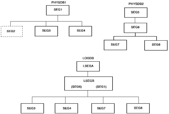
Figure 46. Hierarchies of sample databases
Sample DBD for a Logical Database
LSEGB is the concatenated segment in this example. The SEGM statement for the concatenated segment indicates that SEG6 in PHYSDB2 is the logical child and SEG1 in PHYSDB1 is the destination parent. The DBDs shown in Figure 48 indicate that SEG6 is the real logical child.
        DBD         NAME=LOGDB,ACCESS=LOGICAL
        DATASET     LOGICAL
        SEGM        NAME=LSEGA,SOURCE=((SEG5,PHSDB2))
        SEGM        NAME=LSEGB,PARENT=LSEGA,
                         SOURCE=((SEG6,DATA,PHYSDB2),(SEG1,DATA,PHYSDB1))
        SEGM        NAME=SEG3,PARENT=LSEGB,((SEG3,PHYSDB1))
        SEGM        NAME=SEG4,PARENT=LSEGB,SOURCE=((SEG4,PHYSDB1))
        SEGM        NAME=SEG7,SOURCE=((SEG7,PHYSDB2)),PARENT=LSEGB
        SEGM        NAME=SEG8,SOURCE=((SEG8,PHYSDB2)),PARENT=LSEGB
        DBDGEN
        FINISH
        END
Figure 47. Sample DBD for a logical database
Sample DBDs for Two Physical Databases
According to these DBDs, SEG2 in PHYSDB1 is the virtual logical child segment, and SEG6 in PHYSDB2 is the real logical child segment.
        DBD         NAME=PHYSDB1,ACCESS=HDAM
        DATASET     DD1=HDAM1,DEVICE=3350,BLOCK=2048,SCAN=3
        SEGM        NAME=SEG1,PTR=TWINBWD,RULES=LLV
        FIELD       NAME=(FIELD1,SEQ,U),BYTES=60,START=1
        FIELD       NAME=FIELD2,BYTES=15,START=61
        FIELD       NAME=FIELD3,BYTES=75,START=76
        LCHILD      NAME=(SEG6,PHYSDB2),PAIR=SEG2,PTR=DBLE
        SEGM        NAME=SEG2,PARENT=SEG1,PTR=PAIRED
                         SOURCE=(SEG6,DATA,PHYSDB2)
        FIELD       NAME=(FIELD4,SEQ,U),BYTES=21,START=1
        FIELD       NAME=FIELD5,BYTES=20,START=22
        SEGM        NAME=SEG3,BYTES=200,PARENT=SEG1
        FIELD       NAME=(FIELD6,SEQ,U),BYTES=99,START=1
        FIELD       NAME=FIELD7,BYTES=101,START=100
        SEGM        NAME=SEG4,BYTES=100,PARENT=SEG1
        FIELD       NAME=(FIELD8,SEQ,U),BYTES=15,START=1
        FIELD       NAME=FIELD9,BYTES=15,START=51
        DBDGEN
        FINISH
        END


        DBD         NAME=PHYSDB2,ACCESS=HDAM,RMNAME=DLZHDC20,7,700,250
        DATASET     DDI=HDAM2,DEVICE=3350,BLOCK=2048,SCAN=3
        SEGM        NAME=SEG5,BYTES=31,PTR=TWINBWD,RULES=(VLV)
        FIELD       NAME=(FIELD9,SEQ,U),BYTES=21,START,TYPE=P
        FIELD       NAME=FIELD10,BYTES=10,START=22
        SEGM        NAME=SEG6,
                         PARENT=(((SEG5,DBLE),(SEG1,P,PHYSDB1)),
                         BYTES=80,PTR=(LPARNT,TWINBWD),RULES=VVV
        FIELD       NAME=(FIELD11,SEQ,U),START=1,BYTES=60
        FIELD       NAME=FIELD12,BYTES=20,START=61
        SEGM        NAME=SEG7,BYTES=20,,PTR=T
                         PARENT=((SEG6,SNGL))
        FIELD       NAME=FIELD13,BYTES=9,START=1
        FIELD       NAME=FIELD14,BYTES=11,START=10
        SEGM        NAME=SEG8,BYTES=75,PTR=T
                         PARENT=(SEG6,SNGL)
        FIELD       NAME=FIELD16,BYTES=50,START=1
        FIELD       NAME=FIELD17,BYTES=25,START=51
        DBDGEN
        FINISH
        END
Figure 48. Sample DBDs for two physical databases
Sample CA IDMS/DB Data Structure Diagram
The data structure diagram shown in this illustration depicts the CA IDMS/DB schema for the database corresponding to the DBDs shown in Figure 48.
Figure 49. Sample CA IDMS/DB data structure diagram
Sample PCB Section
Figure 45 through Figure 49 are the sources for this sample PCB SECTION.
       PCB SECTION.
          PCB ACCESS METHOD IS HDAM
            DBDNAME IS LOGDB
            PROCESSING OPTIONS ARE A
            POSITIONING IS SINGLE.
          SEGMENT NAME IS LSEGA RECORD NAME IS REC5
          SEGMENT NAME IS LSEGB RECORD NAME IS REC6
            PARENT IS LSEGA THRU SET REC5-REC6
            LOGICAL DESTINATION PARENT IS REC1
            THRU SET REC1-REC6
            INSERT RULES ARE VIRTUAL,VIRTUAL,LOGICAL
            REPLACE RULES ARE VIRTUAL,VIRTUAL,VIRTUAL
            ACCESS METHOD IS HDAM
            USE IS DATA,DATA.
            SEGMENT NAME IS SEG3 RECORD NAME IS REC3
              PARENT IS LSEGB THRU SET REC1-REC3
              USE IS DATA.
            SEGMENT NAME IS SEG4 RECORD NAME IS REC4
              PARENT IS LSEGB THRU SET REC1-REC4
              USE IS DATA.
           SEGMENT NAME IS SEG7 RECORD NAME IS REC7
              PARENT IS LSEGB THRU SET RC6-REC7
              USE IS NOT SENSITIVE.
            SEGMENT NAME IS SEG8 RECORD NAME IS REC8
              PARENT IS LSEGB THRU SET REC6-REC8
              PARENT IS OWNER USE IS DATA.
Figure 50. Sample PCB SECTION
|
Copyright © 2013 CA.
All rights reserved.
|
|