

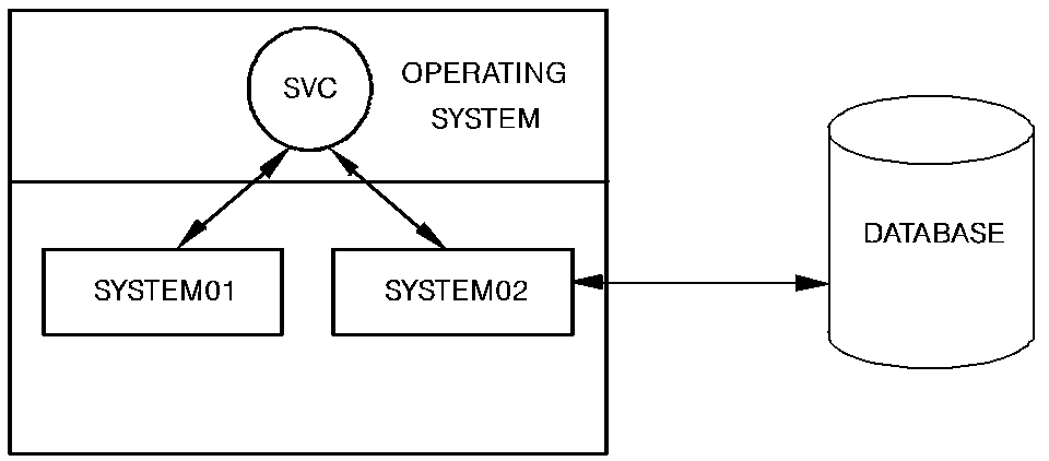
A CA IDMS DDS network consists of multiple nodes connected by the SVC or a telecommunications line, as follows:
Data and application requests are transferred between the two nodes through the SVC.
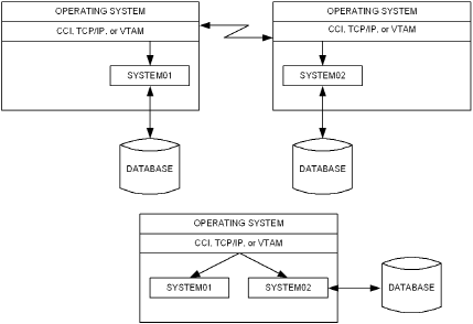
Use of CCI, TCP/IP, or VTAM in a CA IDMS DDS environment is illustrated as follows:
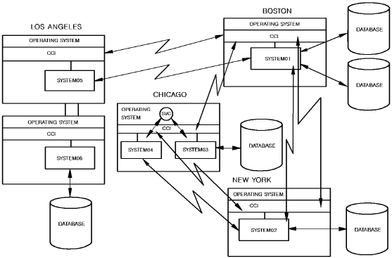
In a network, a node can be connected directly (by way of SVC or a teleprocessing line) to any number of other nodes. If two nodes are connected directly, communication between them takes place by way of this direct connection. If two nodes are not directly connected, communication between them takes place by way of one or more nodes that are directly connected to the host and target nodes. The following illustration shows a sample CA IDMS DDS network.
The nodes in New York and Boston can communicate by way of a direct connection. However, node SYSTEM06 in Los Angeles would communicate with node SYSTEM01 in Boston by way of SYSTEM05.
CA IDMS DDS network configuration is defined through DC/UCF system generation procedures. In addition to standard system generation entries, the system generation of each system that participates in the network includes entries to:
The user can obtain reports on the generation of nodes through the Data Dictionary Reporter (DDR).
Note: For more information about CA IDMS DDS system generation, see Chapter 3, "CA IDMS DDS System Generation".
Facilities are available that allow the user to alter the network configuration as necessary.
Note: For more information about managing the network, see Chapter 4, "CA IDMS DDS System Operations".
Within a network, the CA IDMS DDS controls the selection of the path along which application requests are transferred between nodes. Path selection and global and local databases are discussed in Chapter 2, "Network Design Considerations".
The remainder of this manual provides information essential to the design and implementation of a CA IDMS DDS network.
|
Copyright © 2013 CA.
All rights reserved.
|
|