

When you create a new ER diagram, ERwin always creates a blank diagram. You must select members for the diagram.
To select members for a diagram
The Diagram Editor opens.
The diagrams available in the selected model or subject area are displayed.
Displays objects that you can include as members of the selected diagram. Select one of the following options to include members to the diagram:
Moves the selected objects to the Included Objects section.
Moves all the objects in the Available Objects section to the Included Objects section.
When you select an object that you want to include in the diagram and click this icon, opens the Spanning Neighborhood dialog. Make your selections for the following options:
Ancestors
Specifies the number of ancestors to include in the diagram. Ancestors are the parents of an entity. Select All or select Level and enter the number of ancestors to include. Consider the following example:
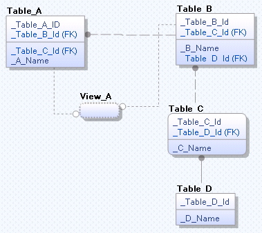
In this example, if you select Table _C and enter 2, the parent of Table_C, which is Table_B (level 1) and the parent of Table_B, which is Table_A (level 2) are included. If you select View_A and enter 2, only Table_A is included.
Descendants
Specifies the number of descendants to include in the diagram. Descendants are the children of an entity. Select All or select Level and enter the number of descendants to include. In the previous example, if you select Table_A and enter 2, the children of Table_A, which are Table_B and View_A (level 1) and the child of Table_B, which is Table_C (level 2) are included.
Opens the Diagram Editor. From the Include all objects contained in list, select the diagram from which you want to include objects.
Displays objects that are currently included as members of the selected diagram. Select one of the following options to remove members from the diagram:
Displays all the objects in the current model in the Included Objects section.
Remove the selected objects from the Included Objects section and moves them to the Available Objects section.
Removes all the objects from the Included Objects section and moves them to the Available Objects section.
When you select an object you want to exclude from the diagram and click this icon, opens the Spanning Neighborhood dialog. Make your selections for the following options:
Ancestors
Specifies the number of ancestors to exclude from the diagram. Select All or select Level and enter the number of ancestors to exclude.
Descendants
Specifies the number of descendants to exclude from the diagram. Select All or select Level and enter the number of descendants to exclude.
Opens the Diagram Editor. From the Remove all objects contained in list, select the diagram from which you want to remove objects. The objects are removed from the current diagram.
Opens the object editor dialog so that you can edit the selected object.
If you have diagrams for specific sections of a model, you can include objects from one diagram into another.
To include objects from another diagram
The ER Diagram Editor opens.
The Members tab opens.
The ER Diagram Editor appears.
All the objects in the diagram except shapes, appear in the Included Objects section of the Members tab.
Note: The Include all objects contained in another diagram option includes only model objects and not drawing objects.
To remove the objects included from another diagram, click the Remove all objects contained in another diagram icon (![]() ).
).
All the objects that are part of another diagram are removed from the Included Objects section and displayed in the Available Objects section.
The selected diagram objects are added to the current diagram in the same position as in the original diagram. If the diagram had objects before you used this option, you may find the new objects overlap with the existing ones.
You can sort the diagram or subject area members in the Available Objects and the Included Objects sections. The toolbar in these sections has the following sort options:
Specifies that the list is sorted in alphabetic order of the name of the object.
Specifies that the list is sorted in reverse alphabetic order of the name of the object.
Specifies that the list is sorted in the alphabetic order of the owner of the object, and then the name of the object.
Specifies that the list is sorted in the reverse alphabetic order of the owner of the object, and then the name of the object.
You can display the name of the diagram or subject area members in various formats in the Available Objects and the Included Objects sections. The toolbar in these sections has the following options:
Opens a menu so you can select to show object names as either logical names or physical names. When you select one of the options, the toolbar button changes to provide you a visual indication of your choice:
Note: The Logical Names option does not display if you are working in either a logical-only or physical-only model.
|
Copyright © 2013 CA.
All rights reserved.
|
|