

CA AppLogic contains strict network configuration enforcement and does not work on systems that fail to conform to the documented certified network configuration. Do not use CA AppLogic on systems that have bypassed the documented certified configuration.
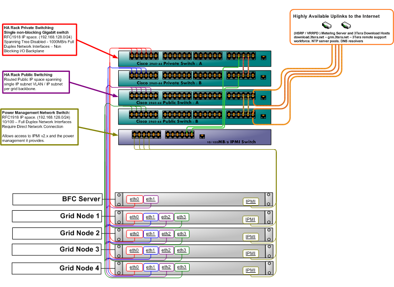
CA AppLogic supports both redundant and non-redundant network wiring. The example diagram shows the typical setup of a grid with redundant wiring. A typical grid consists of two or more commodity servers that connect through Gigabit Ethernet (GbE). Each server has four network interfaces, of which two must be at least GbE. Two of these ports connect to a network that forms the grid backbone (Private Network), these must be the GbE or faster interfaces. The other two ports connect to the public network and access the rest of the datacenter, the public Internet (Public Network), or both. CA AppLogic assumes that the backbone network is private and secure. Implement the backbone using separate GbE or faster switches that are not connected to any other network to achieve this privacy and security.
Each server may also have an IPMI card that connects to a separate switch for power management (normally connected to the backbone network as well). The IPMI ports can also be connected directly to the backbone switch, if it has enough ports, and an additional switch cannot be installed. If you want to have your servers IPMI power-controlled by CA AppLogic, they should be on a network that is accessible to both the BFC and the grid controller. For the most secure setup, you should allocate addresses from the backbone subnet for this purpose as that is accessible to the BFC and Controller, but not generally available to the outside environment.
The following diagram shows an example of a four node grid with a fifth node for the BFC server:
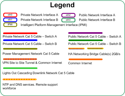
Use the following legend to navigate the diagram:
Specifies HA Rack Private Switching in a single, nonblocking Gigabit switch:
Specifies HA Rack Public Switching with a routed Public IP space spanning single IP subnet VLAN / IP subnet per grid backbone.
Specifies the Power Management Network with the following information:
The legend provides the following information:
You can also use simple, nonredundant wiring with a configuration similar to the previous diagram, but with a single switch for each network.
Important! While redundant wiring allows uninterrupted grid operation, even in case of complete failure of one network switch, all switches must be operational during grid install or maintenance. For example, adding or removing servers or installing hotfixes. This requirement is because the BFC server is assumed to be wired nonredundantly (as shown in the diagram). Minor degradation such as a missing or broken cable on one server is tolerable, but should be avoided during the installation and maintenance to maintain stability.
If you use multiple switches for redundancy, as shown in the previous diagram, enable a link-layer discovery protocol on the switches. CA AppLogic supports the following protocols:
Consider the following information about mixing hardware from different manufacturers:
CA AppLogic also requires that the backbone network provides full non-blocking Gigabit or 10 Gigabit Ethernet connectivity between any two servers of the same grid. In practice, this requirement means that the size of a single grid is limited by the number of ports on the backbone switch(es). Larger grids can be formed by using enterprise grade switches available from Cisco, Dell, Extreme Networks, HP and other vendors, which can have more than 128 ports. Verify that the Spanning Tree Protocol (STP) is disabled on the backbone switches. For the external network, 100 Megabit, 1 Gigabit, or 10 Gigabit Ethernet is allowed.
The CA AppLogic software is installed on each server prior to adding it to the grid. All servers use the same software image; as part of configuring the grid, where one of the servers is designated as primary host and runs the management portion of the system (the grid controller -a virtual machine using part of the physical server's resources). The other servers serve as secondary hosts that can run the controller virtual machine if the primary server fails. The operator manages the grid by accessing the server designated as a controller through a browser, an SSH session, or with an external application through an HTTP-based API.
You can use most readily available commodity servers to build a CA AppLogic grid. The servers require at least an Intel or a compatible AMD x86_64 processor running at 1GHz or better, with support for either Intel-VT or AMD-V virtual machine extensions. This support includes a BIOS capable of enabling these extensions at boot, having at least 2GB of RAM per CPU core, 200GB of ATA/SATA or SAS storage, and 2 Gigabit Ethernet or faster interfaces (four interfaces for redundant setup). When you run web applications, multiple larger high-speed, low latency hard disks and more memory generally improve performance more effectively than raw CPU speed and more CPU cores. Shared storage, such as SAN, NAS or a common file system is not required.
Because each CA AppLogic grid contains its own mirrored storage, you do not need to use any type of hardware RAID on the servers. We recommend that you disable or replace the RAID hardware on all servers used in a grid. You may use nonredundant striping (raid0) for improved disk I/O bandwidth (useful only on hardware with multiple SATA channels that can work in parallel). Some customers use CA AppLogic with their own RAID solutions, but these types of configurations have not been certified or tested.
The servers may also have IPMI configured for server management (power control). CA AppLogic uses IPMI to power-cycle servers that lose connection to the grid. Users can power-cycle, power-down, or power-up servers through CA AppLogic if IPMI is configured for the servers. CA AppLogic 2.7+ has been certified to work with the following server management configurations used for server power control:
The following IPMI configurations may work but have not been certified by CA Technologies:
CA AppLogic supports the following variations of this configuration:
You can configure CA AppLogic to run on a single server, provided that the server has enough resources for the applications that you want to run on the grid. Users typically use single-server grids for CA AppLogic evaluation and testing, eliminating the need for large amounts.
Important! Single server grids do not have any of CA AppLogic's high-availability features.
You can configure CA AppLogic so that as many as 31 separate, independent CA AppLogic grids share the backbone network. This sharing makes it easy to implement smaller "private grids" for customers who do not want to share hardware with anyone while using reasonably sized GbE switches.
This configuration eliminates all possible single points of failure in the local rack environment within the data center. For example, any of the following could fail and network traffic would continue to flow uninterrupted: a single network interface, switch port, an entire switch, a cable, or upstream link.
Utilize the standard rack or highly available rack configuration to place upstream physical hardware devices such as firewalls, routers, load balancers, VPN, IDS, or IPS and similar security devices in-front of the rack of the servers to provide additional layers of security or redundancy within the grid environment.
Use redundant power supply units whenever available as an option to provide some level of redundancy against a power strip or upstream PDU (power distribution unit) failure within the local data center environment.
Finally, keep in mind that because CA AppLogic distributes applications automatically and dynamically across the grid, it is not necessary to use the latest top of the line servers when building CA AppLogic grids. Due to factors such as limitations on memory bus and peripheral bus throughput, a larger number of older servers is quite likely to outperform a similarly priced grid built from newer machines.
The server nodes within a grid do not need to be identical, but should be similar. For example, if you are using an array of hosts that are all dual-socket quad-core CPUs, the clock speeds could be several hundred megahertz or more off and not cause any problems. However, when dealing with other components (such as directly attached storage), take care to provide matching types of disks. Do not mix SAS and SATA disks across an array of hosts within the same grid backbone.
Contact CA Technologies for more details or questions related to hardware that may be used within your grid environment. You can find the hardware configurations known to work with CA AppLogic in the Hardware Compatibility List.
|
Copyright © 2013 CA Technologies.
All rights reserved.
|
|