

Use the following chart to plan your grid deployment:
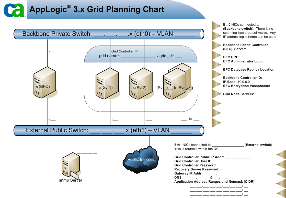
The following list describes example values that you can enter in the chart:
The General tab of the Administration section enables you to modify the general properties of the BFC. Properties include the Backbone controller ID, Grid IDs, External DNS servers, and external storage parameters.
Note: If you select LDAP as the authentication method, then a global user is only recognized in the global directory service if its entry uses one of the following basic object classes for a person:
In addition, a group in the global directory service is only recognized if its entry uses one of the basic object classes for a group (groupOfNames and groupOfUniqueNames).
Follow these steps:
The Administration page appears.
The 'network number' portion of the CA AppLogic® 'grid id'. Value should be between 1..254. All grids that created by this BFC will use this as the network number portion of their ID. This field can only be modified when no grids are configured.
List of grid IDs or ranges to be used by this BFC instance. Valid values are 1-31.
Base address for the IP space used by grid appliances. Must be a class A network, and either 10.0.0.0 or 1.0.0.0. Use 10.x.x.x unless you are installing in an environment where the 10.x.x.x subnet is already in use. This field can only be modified when no grids are configured.
The Account name that is assigned to the grid operator by CA Technologies. This setting is required when installing a new grid and it must be a valid name that is registered in the CA user database.
Name of a file containing a private SSH key identifying the user account.
Enables you to specify that the default authentication is Local, LDAP, or Active Directory. This setting determines how CA AppLogic® authenticates a user using Role Based Access Control.
Primary and secondary DNS servers that are passed to CA AppLogic® grids.
Your changes are saved and the general properties of a grid are configured.
The Versions tab on the Administration page enables you to configure the settings to download the latest CA AppLogic® grid software.
Follow these steps:
The Administration page opens.
Locally-accessible directory that contains the available CA AppLogic® versions. For example, path/to/my/dir. Do not include the actual download folder name in the path. That is, do not indicate path/to/my/dir/3.1.8. The version downloads directory must be readable and writable by the bfcadmin user. If a user other than bfcadmin creates the directory, you may not have adequate permissions for the directory to download the software. This field is required.
Note: Do not use the /home/bfcadmin folder as your download directory. If you uninstall the BFC, this folder is removed.
Specifies the server from which you download the CA AppLogic® versions. For example, download.3tera.net.
Enables you to test the download server.
Location of the download key file that is supplied by CA. The file should reside on your workstation. Click Browse to locate and select the file. Click Reset to reset the file.
The download user for grid software updates.
You can now work with software versions displayed on the Downloads page.
You must have create a backbone network before you can create your grids. CA AppLogic® only supports one backbone network. Typically, the address of the backbone network is 192.168.0.0/24.
Follow these steps:
The Administration page opens.
The Add a Backbone Network dialog appears.
Base IP address of the network.
The length of the subnet bits in the netmask. There is a one-to-one correlation between CIDR prefix length and the traditional IP netmask. For example, 24.
The Configure New Network dialog appears.
IP range for the grid.
The Start, Stop, and Size fields auto-populate based on the network you select. You can change these fields as needed.
First IP in the IP range for the grid.
Last IP in the IP range for the grid.
You must have at least one external network before you can create your grids. Use this procedure to create the external network.
Follow these steps:
The Administration page opens.
The Add an External Network Dialog opens.
Network address of the subnet and this address is not used for assigning to any other nodes. For example, 155.35.86.0.
The length of the subnet bits in the netmask. There is a one-to-one correlation between CIDR prefix length and the traditional IP netmask. For example, 24.
Gateway network address of the external network. Gateway IP is required only for networks that allow access beyond the subnet, but you may have it defined on “private” networks too if desired. For example, 155.35.86.1.
The Configure New Network dialog opens.
Specifies the IP range for the grid.
The Start, Stop, and Scope fields auto-populate based on the network you select. You can change these fields as needed.
Specifies the first IP in the IP range for the grid.
Specifies the last IP in the IP range for the grid.
Indicates whether the range is hardware or application related for external networks.
Note: The hardware and application IPs do not have to be on the same network. If you want to configure a different network for each, repeat steps 3 through 7 and specify the opposite scope in step 7.
CA AppLogic® creates the external network.
If your grid nodes have IPMI capability, you can specify power network settings for your grid network from the BFC. The power network settings allow the BFC to intelligently control the power management operations (such as, power cycle and power off) on grid nodes.
Note: If your nodes have IPMI enabled, then you need to specify the Power IPs of those nodes in the power network.
Follow these steps:
The Administration page opens.
The Add an External Network Dialog opens.
Network address of the subnet and this address is not used for assigning to any other nodes. For example, 192.168.0.0.
The length of the “subnet” bits in the netmask. There is a 1-1 correlation between CIDR prefix length and the traditional IP netmask. For example, 24.
Gateway network address of the external network. Gateway IP is required only for networks that allow access beyond the subnet, but you may have it defined on “private” networks too if desired. For example, 192.168.0.1.
A new page opens where you can specify the following fields with the correct set of IPs.
IP range for the grid.
The Start, Stop, and Scope fields auto-populate based on the network you select. You can change these fields as needed.
First IP in the IP range for the grid.
Last IP in the IP range for the grid.
You can add and configure VLANs for a network on the Administration page, Networks tab, External tab. After you add a VLAN, you can select IP ranges you have specified in the VLAN for creating tagged VLAN grids. You can create multiple VLANs associated with a subnet with overlapping IP ranges. Generally, this allows you to reuse IP addresses provided that the IPs are not routed outside the BFC environment.
Note: Do not mix tagged VLANs and non-VLAN networks on the same grid.
Follow these steps:
The Administration page opens.
For each network, a VLANs button appears at the end of the row.
The VLANs dialog opens.
The Add a VLAN dialog opens. Specify the following information:
Specifies the VLAN ID.
Lists the name of the network you are working with.
A dialog opens that allows you to indicate VLAN parameters.
The Add/Edit IP Range dialog opens. Indicate the following parameters for the VLAN:
Indicates the IP range to use. Select a range from the drop-down list.
The Start and End fields are populated based on your choice. Accept the defaults or edit the fields.
The Add/Edit IP range dialog closes and you return to the VLAN parameters page.
The VLAN parameters page closes and you return to the VLANs dialog.
The VLANs dialog closes and you return to the Administration page.
You can now assign your VLAN and corresponding application IPs to a grid when you create a new grid, or work with grid properties on the Network tab of the Grid properties page.
The BFC enables you to configure the Automatic Discovery feature for the current backbone network as needed. Automatic Discovery is off by default.
Follow these steps:
The Administration page opens.
Note:When the server discovery is off, new servers are not discovered when they are powered on. In addition, server discovery must be turned off before you can specify the Discovery Mode.
You are prompted to turn on Server Discovery.
Note: Discovery lists can only be edited while discovery is off. If you decide to change the discovery mode later, any existing quarantine lists you created are deleted.
|
Copyright © 2012 CA.
All rights reserved.
|
|